


Machine Vision Lenses for AI, Robotics, and Micro-Inspection
A buyer-focused guide to matching standard, macro, microscope, telecentric, line-scan and SWIR optics to AI inspection and robotic working geometry.
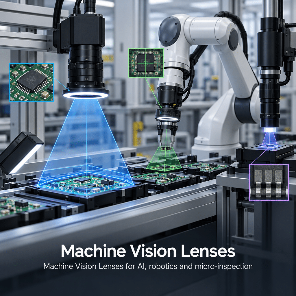
Key Takeaways
Machine Vision Lenses should be selected from the inspection decision, smallest relevant feature and installation geometry—not focal length alone.
- Calculate field of view and object-side pixel scale before comparing lens resolution claims.
- Reserve physical space for lighting, robot motion and part-height variation when setting working distance.
- Use low-distortion or telecentric optics when perspective or magnification changes would consume the measurement tolerance.
- Choose macro or microscope optics only after checking working distance, illumination access and sensor coverage.
- Validate the complete camera, lens, lighting and mount assembly across the intended operating range.
The Short Answer
Machine Vision Lenses for AI, robotics and micro-inspection should be chosen by working backward from the required decision. Establish the field of view, smallest defect or measurement, camera sensor, working distance and lighting path. Standard fixed-focal-length lenses suit many detection and segmentation tasks. Macro or microscope optics address smaller features, while low-distortion or telecentric designs support demanding gauging and robot-coordinate conversion. Line-scan, large-image-circle or SWIR optics are application-specific choices. Final approval should come from testing the complete optical assembly across expected distances, poses, surfaces and production tolerances.
How Machine Vision Lenses Affect AI and Inspection Results
A model cannot recover spatial detail or contrast that never reaches the sensor. The practical role of machine vision lenses is therefore to deliver usable information across the required field—not merely a sharp-looking image at its center.
Detection may tolerate moderate distortion if the part remains distinguishable. Segmentation depends more heavily on stable edges and target-to-background contrast. Pose estimation adds calibration stability, while gauging turns distortion and perspective into possible measurement errors. Official AI and robotics lens guidance likewise recommends starting with the task and accounting for working distance, lighting, motion and calibration rather than field of view alone.
The first specification should be the production decision: presence, class, boundary, coordinate, dimension or defect. Focal length follows from that decision, the sensor and the available geometry.
Machine Vision Lens Selection by Vision Task
Detection, classification and segmentation
For presence and classification, cover the full inspection area with repeatable contrast at the edges as well as the center. A wider view can reduce camera count, but it also assigns fewer sensor pixels to each object feature. Segmentation adds sensitivity to flare, reflections, depth of field and lighting angle because unstable boundaries become unstable masks.
Pose estimation and robotic guidance
Robotics camera lenses must preserve a repeatable relationship between image coordinates and the robot frame. Low distortion simplifies calibration, but mechanical rigidity, focus locking, back-focus control and recalibration policy remain part of the system. Computar’s technical guidance specifically identifies mount rigidity, locking hardware and calibration across poses and distances as relevant controls.
Gauging and dimensional measurement
Measurement requires more than high pixel count. Magnification must remain predictable over the allowed part-height range, and residual distortion must either fit the error budget or be calibrated. Opto Engineering’s optics guidance identifies telecentric designs for precise measurement and for limiting perspective errors caused by positioning variation or three-dimensional geometry.
Micro-defect inspection
Lens selection for defect detection starts with the smallest defect that changes the pass-fail result—not the smallest mark visible under ideal conditions. Macro lenses or objectives may supply the needed magnification, but shorter working distance can restrict darkfield, coaxial or ring-light placement. A higher-magnification view can also reduce throughput or require additional camera positions.
Application Matrix: Match Lens Type to Feature Size and Working Geometry
Use this matrix to narrow machine vision lens options by task, feature scale, and installation geometry.
| Vision task | Inspection priority | Working geometry | Recommended category | Key checks |
|---|---|---|---|---|
| Detection and classification | Presence, class separation and contrast | Moderate field with lighting access | Standard fixed-focal-length lens | Sensor coverage, aperture, edge quality, distortion |
| Segmentation | Stable target boundaries | Lens position may be driven by reflection control | Standard or specialized lens | Flare, contrast, depth of field, lighting clearance |
| Pose estimation | Repeatable feature coordinates | Standoff, vibration, occlusion and robot path | Low-distortion or ruggedized optic | Calibration stability, rigidity, field coverage |
| Gauging | Consistency across the usable field | Part-height and perspective variation | Low-distortion or telecentric lens | Magnification stability, calibration, tolerance |
| Micro-defect inspection | Small-feature contrast | Often limited working and lighting space | Macro lens or microscope objective | Magnification, working distance, illumination path |
| Continuous web or large sensor | Wide or continuous coverage | Long sensor and substantial installation envelope | Line-scan or large-image-circle lens | Image circle, uniformity, mount and sensor match |
When a standard lens is the practical choice
A standard fixed-focal-length lens is usually the starting point when the field is moderate, part-height variation is controlled and calibrated distortion meets the application tolerance. Catalog availability and adjustable aperture can simplify prototyping. Confirm performance at the intended magnification and working f-number rather than relying on focal length alone.
When to use macro lenses for machine vision
Macro optics fit close-range inspection where a small field must fill much of the sensor. Verified manufacturer documentation describes macro lenses as close-working-distance optics for high-precision tasks. The trade-off is packaging: adequate focus does not guarantee enough room for the light, protective window or moving tooling.
When microscope objectives are required
Objectives become candidates when the relevant feature scale demands higher magnification than a practical macro arrangement can provide. Numerical aperture, objective working distance, tube-lens compatibility and field coverage then become system-level decisions. This guide to microscope objectives for inspection examines those dependencies in more detail.
Specialized optics for line scan, large sensors and SWIR
Large sensors need a lens image circle that covers the full active area. Continuous webs may favor line scan, while area scan remains suitable for discrete objects; review line scan vs area scan imaging system selection before fixing the optical architecture. For long sensors or reflective surfaces, use the additional line scan lens selection criteria.
Calculate the Optical Requirements Before Choosing a Lens
Field of view and object-side resolution
Set the field of view from the part envelope plus required positional tolerance. Then calculate object-side pixel scale:
object-side pixel scale = field dimension ÷ sensor pixels across that dimension
Illustrative calculation, not a detection guarantee: a 100 mm field mapped across 2,000 pixels gives 0.05 mm per pixel. A 0.15 mm feature spans three pixels only under ideal geometric mapping. Whether it is reliably detected still depends on contrast, sampling orientation, focus, motion, noise, processing and lens performance.
This calculation prevents a common purchasing error: paying for more camera pixels while the lens, magnification or contrast remains the limiting element. Manufacturer guidance confirms that useful results depend on camera resolution and pixel size as well as the optics.
Magnification, distance and compatibility
For a first-order layout, optical magnification can be estimated as sensor dimension divided by the corresponding object field. Treat that as a geometry estimate; the selected lens data and a physical trial should establish the actual field and focus position.
Working distance must accommodate the robot approach, fixtures, part-height range, illumination and maintenance access. Also verify image circle, mount, sensor format, pixel pitch and back-focus requirements. A mechanically compatible mount does not prove optical coverage or adequate corner performance.
Calibration, Measurement and Robot Repeatability
Distortion correction can improve coordinate mapping, but calibration does not remove blur, focus drift or mechanical movement. Validate the calibration at the distances and poses the machine will use, not solely at one setup position.
Telecentric optics are justified when perspective error or magnification change would consume too much of the tolerance. Schneider-Kreuznach’s industrial lens documentation describes telecentric lenses as maintaining constant object magnification despite distance variation and identifies them for dimensional measurement. That benefit does not make every telecentric design suitable: field size, working distance, sensor coverage, lighting path and package diameter still constrain selection.
For robot guidance, document whether calibration is eye-in-hand or fixed-camera, the accepted pose range, how focus is locked and what event triggers recalibration. These controls often matter as much as the nominal distortion specification.
Lighting and Surface Behavior Can Set the Lens Choice
A lens that fits optically may fail mechanically once illumination is added. Ring lights need front clearance; low-angle lights require lateral space; coaxial illumination needs a compatible optical path. Robot grippers and tooling must not cast shadows in production poses.
Glossy metal, glass, curved surfaces and coatings can create highlights that hide edges or imitate defects. Lighting geometry and polarization should be evaluated with representative materials before finalizing aperture and exposure. Stopping down can increase depth of field, but verified manufacturer guidance notes the accompanying diffraction trade-off. More illumination or a strobe may be needed to retain a short exposure for moving parts.
Visible contrast is not always sufficient. Schneider-Kreuznach documents SWIR optics optimized for 800–1800 nm and applications including moisture and wafer inspection. The camera, lens coatings, illumination and material response must all suit the selected band; SWIR imaging for defect detection provides a system-level overview.
How to Choose a Machine Vision Lens: Buyer Checklist
Before requesting a recommendation or approving an OEM design, record:
- The inspection decision and the smallest relevant feature or tolerance.
- Required field of view, part envelope and positional variation.
- Camera sensor format, active resolution, pixel size and mount.
- Available working distance and permitted lens envelope.
- Lighting type, angle, wavelength and physical clearance.
- Part motion, exposure limit, vibration and environmental constraints.
- Distortion, calibration and depth-of-field requirements.
- Validation points at field center, edges and expected operating extremes.
Test representative good and bad parts across distance, pose, speed and surface variation. Record aperture, focus setting, spacers, lighting geometry and calibration version so the approved setup can be reproduced.
Need selection support? Share the sensor, field of view, minimum feature, working distance, material, lighting layout and required inspection or robot-guidance task.
When to Specify a Custom Optical Assembly
A custom design becomes reasonable when no catalog lens satisfies the combined optical and mechanical envelope. Typical triggers include a nonstandard illumination path, constrained package, special wavelength, large sensor, application-specific distortion target or a working distance unavailable from standard products.
High-throughput equipment can also expose competing requirements: more depth of field may call for a smaller aperture, while motion demands a shorter exposure. If available illumination cannot reconcile those conditions, changing magnification, sensor sensitivity, optical architecture or mechanical handling may be more effective than changing focal length.
Review available optical lens and lens assembly options before committing to custom engineering. For an OEM program, validate the prototype configuration, tolerance-sensitive spacings, focus-lock method, coating or spectral requirements, mounting datum and change-control plan. A custom assembly should solve a documented system constraint, not substitute for incomplete requirements.
Frequently Asked Questions
What information should I provide when requesting a machine vision lens recommendation?
Start with the inspection task, camera model or sensor format, active resolution, pixel size, mount, field of view and minimum relevant feature. Add working distance, part-height variation, lighting arrangement, wavelength, motion, material finish, space limits and calibration or measurement tolerance. Include representative part images if their capture conditions are documented.
Can one lens support both detection and precision measurement tasks?
Yes, if its field coverage, distortion, magnification stability and resolved contrast satisfy both acceptance criteria. Detection often tolerates errors that measurement cannot. Validate the measurement uncertainty across the full field and part-height range rather than assuming a lens selected for classification will also support accurate gauging.
How do I know whether sensor resolution is useful for the smallest defect?
Calculate object-side pixel scale from field size and active pixels, then estimate how many pixels represent the defect. Treat this only as an initial sampling check. Reliable detection also depends on lens performance, contrast, focus, motion, noise, defect orientation and the algorithm’s validated acceptance threshold under production conditions.
What is the difference between a macro lens and a microscope objective?
A macro lens commonly provides close-range imaging in a relatively integrated camera-lens arrangement. A microscope objective is part of a higher-magnification optical system and may require a compatible tube lens. Compare achievable field, numerical aperture, working distance, illumination access, sensor coverage and mechanical integration rather than magnification labels alone.
How should I validate a lens before committing it to an OEM production design?
Test the complete camera, lens, mount and lighting assembly with representative parts at the intended speed. Cover field center and corners, distance and pose limits, surface variation, temperature or vibration conditions where applicable, and known defects. Freeze aperture, focus, spacers, calibration files and acceptance criteria after validation.
Topics
Related Articles
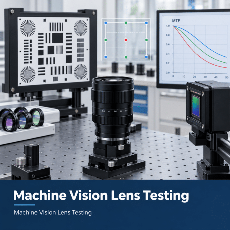
Machine Vision Lens Testing: MTF, Tolerance, and Reliability
11 min read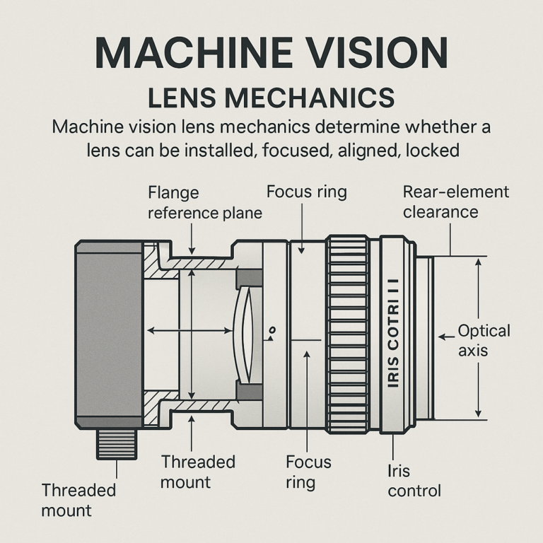
Machine Vision Lens Mechanics: Mounts, Alignment, and Barrels
12 min read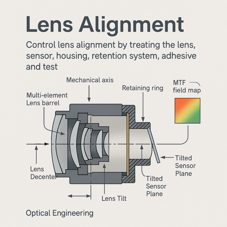
How to Control Lens Alignment, Tilt, Decenter, and MTF Degradation
11 min readAbout SUPERIOR OPTICS
SUPERIOR OPTICS specializes in CCTV lenses, machine vision optics, and custom optical solutions for security, industrial imaging, and specialty applications. We also provide professional lens selection and application support.