


Microscope Objective Selection for OEM Micro-Inspection Systems
A buyer-focused method for balancing resolution, sensor coverage, working distance, tube-lens architecture, illumination access, and production tolerance in OEM micro-inspection systems.
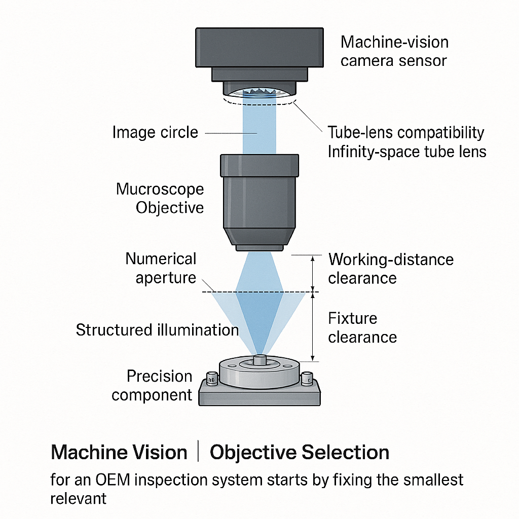
Key Takeaways
Microscope Objective Selection should begin with the feature, inspection area, clearance, and process variation—not the magnification printed on the barrel.
- Calculate object-side field coverage before selecting nominal magnification.
- Evaluate numerical aperture, pixel sampling, illumination, and target contrast as one detection chain.
- Reserve enough working distance for fixtures, lighting, protective windows, motion, and collision margin.
- Match infinity-corrected objectives to the intended tube lens, correction strategy, thread, and optical spacing.
- Validate representative parts across sensor corners and expected production tolerances before releasing the optical design.
The Short Answer
Microscope Objective Selection for an OEM inspection system starts by fixing the smallest relevant feature, required object-side field, sensor format, clearance, and part-height variation. Magnification alone cannot establish detection performance. The objective’s numerical aperture, working distance, image coverage, tube-lens architecture, camera sampling, and illumination must operate as a compatible system. Shortlist only configurations that cover the active sensor and fit the mechanical envelope, then validate contrast, focus tolerance, corner quality, and repeatability with representative parts.
A 20× label does not show whether the objective can see the complete inspection area, clear the fixture, cover the camera corners, or produce sufficient defect contrast. OEM buyers need an optical-path decision, not an isolated objective specification. Available configurations can be reviewed under Microscope Objectives and Eyepieces, but feasibility depends on the complete system.
Start With the Inspection Requirement, Not Nominal Magnification
Define the detectable feature
Separate the smallest physical feature from the smallest feature that must be classified reliably. A scratch may be physically narrow yet detectable because its illumination response creates a wider contrast transition. Conversely, a geometrically resolvable mark can disappear against texture or glare. Record feature dimensions, orientation, reflectivity, acceptable false decisions, and the required contrast mechanism.
The resulting requirement is a system requirement. The objective forms the image, the camera samples it, and illumination determines whether useful contrast reaches the sensor.
Set area, throughput, and variation
Specify the object-side width and height needed in one exposure. If the process permits multiple views, include stage travel, settling time, stitching tolerance, and cycle-time consequences. Also record part-height variation, surface tilt, fixture repeatability, and whether autofocus is available. These conditions establish how much focus margin the production station needs.
Map the mechanical envelope
Working distance must accommodate more than the nominal gap to the part. The stack can include coaxial or oblique lighting, a protective window, fixture walls, robot tooling, contamination controls, and motion clearance. A mechanically unusable objective remains unusable regardless of its optical rating.
Microscope Objective Selection: Evaluate the Core Parameters Together
Microscope objective specifications documented by Nikon identify magnification, numerical aperture, correction, tube-length requirements, and immersion conditions among the information commonly marked on an objective. Those values interact.
Magnification, numerical aperture, and usable field
Magnification determines image scale, not resolution by itself. Numerical aperture influences light acceptance, resolving power, and depth of field. Higher NA can improve resolution, but verified technical guidance also associates it with reduced working distance and depth of field. That trade-off can make a high-NA laboratory configuration sensitive to ordinary production variation.
Usable field is narrower than a nominal field when corner shading, aberration, or illumination nonuniformity prevents reliable inspection. Acceptance criteria should therefore cover the region where the algorithm must operate, including the corners.
Working distance, image circle, and depth tolerance
Objective working distance is measured under defined optical conditions; the integration team still has to allocate physical clearance. Long-working-distance designs create more space for manipulation or lighting, although objective selection guidance from RP Photonics notes that longer clearance often comes with a numerical-aperture compromise.
Field number or stated field limits can help screen candidates, but they should not be treated as automatic proof of camera coverage. The relevant test is whether the full active sensor receives acceptable illumination and image quality through the intended tube lens. The same coverage logic becomes especially significant when assessing lens coverage for sensor dimensions and pixel pitch on long or specialized sensors.
Use Sensor Size and Field of View to Confirm System Coverage
For a first-order estimate, object-side field width equals active sensor width divided by effective system magnification; height follows the same relation. This is an engineering calculation, not a guarantee of usable corner performance.
Illustrative assumption: a camera has an active width of 12 mm and the complete optical path provides 10× effective magnification. The estimated object width is 1.2 mm. If the inspection requires 1.5 mm in one frame, increasing magnification makes the coverage deficit worse. A lower-magnification objective, a larger sensor, multiple views, or another optical architecture is required.
Sampling can be estimated similarly: object-side sample spacing equals pixel pitch divided by effective magnification. That result describes sampling interval, not guaranteed defect detection. Optical transfer, focus, motion, noise, illumination, feature orientation, and decision thresholds still govern performance.
Ask the supplier to identify the supported image field and conditions. Then inspect flat-field response and representative targets at the center, edges, and corners. A sensor that physically receives light may still have unusable peripheral contrast or shading.
Verify Tube Lens Compatibility Before Selecting an Infinity-Corrected Objective
Finite-conjugate and infinity-corrected objectives are different architectures. Verified Nikon guidance states that a finite objective forms its image at a specified intermediate plane, while an infinity-corrected objective requires a tube lens. The two types are not interchangeable merely because their threads appear compatible.
For an infinity system, a useful first-order relation is:
effective magnification = marked magnification × actual tube-lens focal length ÷ design tube-lens focal length
Thus, an objective marked 10× for its manufacturer’s design tube lens will not necessarily remain 10× with another focal length. This relation predicts scale; it does not prove correction quality. Manufacturers may distribute aberration correction between the objective and tube lens, and mounting threads can differ.
A compatibility review should cover the objective model, intended tube-lens focal length and correction, optical spacing, filter or beamsplitter space, thread, parfocal distance, camera mount, and sensor position. Do not approve a mixed-manufacturer path from magnification and thread alone.
Match Numerical Aperture and Resolution to Pixel Sampling and Lighting
An inspection chain can be optics-limited, sampling-limited, contrast-limited, or focus-limited. Adding magnification does not recover detail that the objective fails to transfer. Likewise, greater NA provides little production benefit if coarse pixels, motion, glare, or shallow focus remain dominant.
Start with the required object-space sampling, then assess whether the objective can deliver adequate contrast at that scale. Treat a rule such as “several pixels per defect” only as an initial engineering assumption; the needed sampling depends on feature geometry and the algorithm. Validate it with representative defects rather than presenting one pixel count as universal.
Lighting is part of microscope objective lens selection. Brightfield, darkfield, and epi-illumination create different contrast and packaging demands. Reflective parts may require control of stray reflections; low-angle darkfield needs physical access around the objective. Coaxial illumination may add components in the infinity space and must be included in the spacing review.
Higher NA generally trades depth tolerance for resolving capability. The broader relationship among aperture, depth of field, and diffraction helps explain why the highest available aperture is not automatically the most robust production choice.
Compare Objective Working Distance Against Production-Line Usability
Build a clearance budget from the mechanical model rather than the catalog photograph. Include maximum part height, fixture tolerance, window thickness and mount, lighting hardware, focus travel, stage runout, loading motion, and a collision allowance established by the machine-safety design.
A window can also alter image quality when it was not included in the optical design. Its material, thickness, tilt, coatings, and location should be disclosed during evaluation. The same applies to filters or beamsplitters inserted between an infinity objective and its tube lens.
Longer working distance can solve access problems but may reduce the available NA or require a larger, more specialized assembly. The buyer-facing decision is whether extra clearance is worth the potential loss of resolution, brightness, packaging space, or cost—not whether LWD appears on the barrel.
Selection Table: Choose the Objective Parameter That Governs Each Requirement
For early microscope objective selection, begin with the requirement that is hardest to compromise, then verify the connected parameters before comparing magnification.
| Requirement | Parameter to evaluate | Verify | Common risk | OEM response |
|---|---|---|---|---|
| Smallest feature | NA and resolution | Optical transfer, sampling, contrast | High magnification without usable detail | Test optics, pixels, and lighting together |
| Inspection area | Magnification, field limit, sensor | Object-side field and corners | Target does not fit | Calculate coverage first |
| Part clearance | Working distance | Fixture, lighting, window, motion | Collision or blocked lighting | Set minimum clearance from CAD |
| Infinity integration | Tube-lens compatibility | Focal length, correction, spacing, mounts | Wrong scale or degraded image | Review the complete optical path |
| Height variation | Depth of field and NA | Allowed focus excursion | Defects leave focus | Trade peak resolution for tolerance if needed |
| Reflective defect | Illumination geometry and coatings | Contrast and stray reflections | Resolved feature remains invisible | Test representative surfaces |
| High throughput | Field, focus margin, packaging | Repeatability and cycle-time impact | Laboratory setup fails in production | Preserve integration margin |
A catalog objective is appropriate when its field, correction, interfaces, working distance, and supply requirements fit the platform. If the design requires a nonstandard image field, integrated illumination, unusual packaging, environmental sealing, or a fixed objective-to-sensor module, evaluate custom optical assemblies and lens options instead. That is an engineering inference based on integration needs, not a claim that customization always improves performance.
A Practical Selection Workflow for OEM Micro-Inspection Systems
- Freeze the inspection envelope. Record minimum feature, required field, surface properties, height variation, cycle time, and decision criteria.
- Choose the sensor deliberately. Document active dimensions, pixel pitch, shutter behavior, interface, and required frame rate. Calculate first-order field and sampling.
- Shortlist objective families. Compare magnification, NA, working distance, correction class, field support, immersion requirements, and mechanical interface.
- Complete the optical path. Select the compatible tube lens where required and include illumination, filters, windows, mounts, and focus adjustment.
- Validate with production-representative images. Check center and corners, acceptable and defective parts, height extremes, motion conditions, contamination exposure, and lighting drift.
At the fifth step, Microscope Objective Selection becomes an evidence-based release decision rather than a catalog comparison. Preserve raw images, settings, part conditions, and acceptance thresholds so procurement substitutions can be assessed against the same baseline.
Common Microscope Objective Selection Mistakes
- Choosing magnification first: the required area may no longer fit on the sensor.
- Assuming marked magnification is universal: an infinity objective’s scale depends on its intended tube-lens system.
- Treating NA as the only resolution criterion: sampling, focus, motion, and contrast can remain limiting.
- Checking only the image center: corner shading or degradation may intersect an inspection region.
- Ignoring illumination volume: the selected geometry may not fit around a short-working-distance objective.
- Testing a flat ideal sample only: production height, tilt, texture, and reflectivity can expose a fragile design.
For an objective or optical-path review, share the required feature size, field of view, sensor format and pixel pitch, minimum working distance, tube-lens architecture, illumination concept, windows or filters, and mechanical constraints. Those inputs allow Microscope Objective Selection or a custom-assembly evaluation to begin with defined boundaries.
Frequently Asked Questions
Can a microscope objective be used directly with a machine vision camera?
Yes, but not usually by attaching the objective to the camera without other optics. A finite objective needs its specified image distance, while an infinity-corrected objective requires a compatible tube lens. The mount, sensor position, image coverage, correction strategy, and illumination path must also be checked.
What is the difference between a finite-conjugate and an infinity-corrected microscope objective?
A finite-conjugate objective forms an image at a specified intermediate plane associated with its designed tube length. An infinity-corrected objective sends a collimated beam toward a tube lens, which forms the image. These architectures have different spacing and correction requirements and should not be treated as interchangeable.
How does a tube lens change the effective magnification of an infinity-corrected objective?
Effective magnification scales with the ratio between the installed tube-lens focal length and the focal length for which the objective’s marked magnification was specified. Changing that lens can therefore change image scale. Compatibility still requires verification because magnification alone does not establish correction quality or sensor coverage.
How do I determine whether a microscope objective covers my camera sensor?
Compare the objective and tube-lens system’s supported image field with the sensor’s active diagonal and dimensions. Then verify actual corner illumination, focus, and contrast using the intended optical path. A bright image at every corner does not by itself establish that peripheral quality meets the inspection requirement.
What information should I provide when requesting an objective recommendation for a micro-inspection system?
Provide feature dimensions, required field width and height, sensor model, active dimensions, pixel pitch, working-distance limit, part-height variation, surface properties, illumination concept, tube-lens details, windows or filters, mount constraints, and throughput target. Include representative parts or images and define what constitutes an acceptable detection result.
Topics
About SUPERIOR OPTICS
SUPERIOR OPTICS specializes in CCTV lenses, machine vision optics, and custom optical solutions for security, industrial imaging, and specialty applications. We also provide professional lens selection and application support.