


Telecentric and Line Scan Lenses for Precision Measurement Systems
A buyer-focused engineering comparison of telecentric, line-scan and combined imaging architectures for dimensional gauging, continuous inspection and machine vision metrology.
Key Takeaways
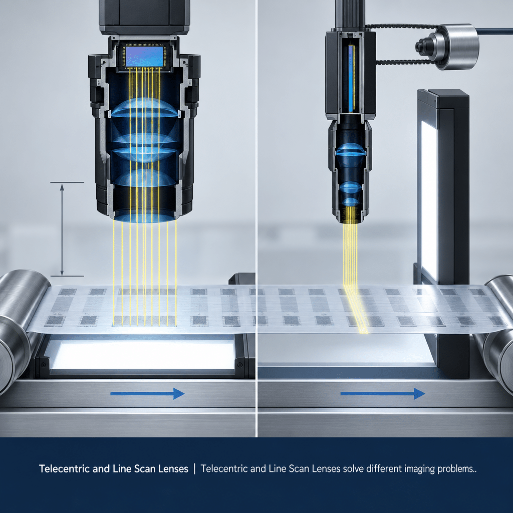
Choosing between Telecentric and Line Scan Lenses depends on whether the dominant risk is perspective-sensitive measurement, continuous object coverage, or both.
- Choose object-space telecentric optics when permitted part-height variation would otherwise change measured magnification.
- Choose line-scan acquisition when motion can present a continuous web, long part or surface one line at a time.
- Combine telecentric geometry with a line-scan sensor only when continuous acquisition also requires stable dimensional scaling.
- Calculate object-side sampling and sensor coverage before comparing mounts, working distances or nominal magnification.
- Calibrate the assembled system and verify error across production position, height and speed limits.
The Short Answer
Telecentric and Line Scan Lenses solve different imaging problems. Telecentric optics constrain the viewing geometry so dimensional scale is less sensitive to permitted object-distance changes. Line-scan systems acquire a narrow row of pixels repeatedly as the object or camera moves, making them suitable for continuous or elongated surfaces. Use both when a moving process also requires perspective-resistant gauging. The defensible choice depends on tolerance, depth variation, sensor dimensions, field width, motion control, illumination access and the validated error budget.
Telecentric vs. Line Scan Lenses: Selection Comparison
Telecentric and Line Scan Lenses for precision measurement systems: architecture comparison
| Selection factor | Telecentric lens approach | Line-scan lens approach | Combined approach | Best-fit scenario |
|---|---|---|---|---|
| Primary objective | Stable dimensional scale | Continuous coverage | Stable scale during continuous acquisition | Match architecture to dominant error |
| Perspective behavior | Reduces sensitivity to object-distance changes | Depends on selected lens geometry | Telecentric control in the measured axis or field | Parts with depth variation |
| Object geometry | Bounded part within object field | Web, long part or moving surface | Moving material requiring gauging | Geometry determines coverage |
| Sensor geometry | Commonly area scan; line scan is available | One-dimensional sensor length | Line sensor plus telecentric optical path | Check sensor length and image circle |
| Working distance | Often constrained by object field and large front optics | Set by field width and installation envelope | Both constraints apply | Confirm mechanical clearance early |
| Motion | Can inspect stationary or indexed parts | Motion constructs the second image dimension | Requires controlled motion and optical stability | Continuous transport |
| Illumination | Backlight often supports edge gauging | Geometry follows surface defect contrast | Uniformity and timing both matter | Select for the feature, not the lens label |
| Calibration | Scale, distortion and alignment remain relevant | Adds motion-axis calibration | Includes optical and motion effects | Validate the complete system |
| Main risk | Oversized, costly optics without measurement benefit | Stretch, compression or nonuniformity | Integration complexity | Use an error budget |
| Typical application | Gauging, metrology, positioned parts | Web and long-surface inspection | Continuous dimensional inspection | Choose from process conditions |
When Each Architecture Is Required
Part height can create measurement error
A conventional perspective lens can make a feature appear larger as it moves toward the camera. Object-space telecentric optics use chief rays that are approximately parallel to the optical axis, producing an orthographic-style view. Manufacturer documentation supports their use where three-dimensional parts or imperfect positioning would otherwise disturb dimensional scale (Opto Engineering’s industrial lens guidance).
Telecentricity is justified when the expected displacement-related error consumes an unacceptable part of the measurement budget. If the part is flat, tightly fixtured and measured at one plane, a calibrated conventional lens may be the smaller and less expensive engineering choice. This distinction is developed further in the comparison of telecentric versus conventional lens accuracy and calibration.
Continuous, wide or long surfaces favor line scan
A line-scan architecture is a process choice as much as an optical choice: relative motion supplies the second image dimension. It fits webs, sheets and long parts that cannot be captured efficiently in one area-scan frame. The lens must cover the line sensor and resolve the required object width; the transport and trigger strategy determine sampling along motion.
Available line scan lenses for inspection should therefore be evaluated against sensor length, pixel pitch, field width, wavelength and working distance—not merely mount type.
When a combined design is defensible
Official technical documentation confirms that telecentric optics can be configured for line-scan sensors. A combined system is appropriate when material moves continuously and the measured edges cannot tolerate ordinary perspective sensitivity. It is not automatically superior: larger optics, restricted installation space and tighter alignment can outweigh the benefit if depth variation is negligible.
How Telecentric Optics Improve Dimensional Measurement
How do telecentric lenses reduce perspective error?
Telecentric optics constrain accepted chief-ray angles so apparent feature size changes less when the object moves within the lens’s specified telecentric range. The remaining change is not zero; Opto Engineering describes it through telecentric slope and also identifies residual distortion as a metrology concern in its telecentric lens technical tutorial.
That distinction matters. Depth of field concerns acceptable sharpness, while telecentric range concerns allowable magnification behavior. A feature may look sharp yet still fail a dimensional error limit if scale changes exceed the budget.
Object-space, image-space and bi-telecentric designs
Object-space telecentricity addresses magnification sensitivity to object displacement. Image-space telecentricity controls chief-ray geometry at the sensor. A bi-telecentric design applies parallel-ray behavior on both sides; according to Schneider-Kreuznach’s telecentric optics documentation, this can reduce sensitivity to small sensor-position errors and support more uniform sensor illumination.
Those benefits come with physical consequences. Telecentric lenses generally need front optics at least as large as the object field they must accept. Buyers should check diameter, mass, mounting stiffness and access for lights before freezing the machine envelope.
Telecentricity does not remove calibration
Distortion, sensor tilt, scale-factor error, focus, edge-threshold behavior and fixture variation remain. Telecentric optics reduce one important error mechanism; they do not certify the assembled measurement system. Calibration must represent the production working distance, inspection plane, aperture, wavelength and focus setting.
How Line Scan Lenses Support Continuous Inspection
Sensor length, field width and pixel geometry
Start with object-side sampling. Under an idealized geometric model:
object sampling = sensor pixel pitch ÷ optical magnification
Hypothetical example: a 7 µm pixel with 0.5× magnification corresponds to 14 µm per pixel at the object. That is sampling, not guaranteed measurement accuracy. Lens contrast, blur, distortion, motion, illumination, calibration and the edge algorithm still influence the result.
The image circle must cover the complete line sensor, including alignment tolerance. Resolution must also remain usable toward the ends of the line, where field-dependent aberrations and illumination falloff can become visible.
Motion, line rate and pixel aspect ratio
As an engineering derivation, square object sampling requires the travel per acquired line to equal object-side sampling across the line. If object sampling is 14 µm, one line should represent 14 µm of travel. At 1 m/s, the idealized requirement is about 71,429 lines/s: 1,000,000 µm/s ÷ 14 µm/line.
This calculation excludes exposure overhead, trigger limits and speed variation. Encoder-referenced acquisition can tie line timing to distance traveled rather than assumed velocity. The design still needs validation during acceleration, deceleration and transport slip.
Uniformity across a wide field
Wide-line inspection can fail at the edges even when the center is acceptable. Evaluate lens contrast, geometric mapping, illumination uniformity and sensor response across the full active length. Flat-field correction may compensate for repeatable brightness variation, but it cannot recover detail that the optics never resolved or remove unstable reflections.
Engineering the Optical Path
Resolve the feature before choosing magnification
Convert the smallest relevant feature or tolerance into required object-side sampling, then assign margin for the algorithm and production variation. Pixel size alone is not a measurement specification. The lens, sensor, illumination and software operate as one chain, a point also emphasized in Opto Engineering’s verified system-selection guidance.
For inspections that do not require telecentricity, review broader machine vision lenses for industrial optics against sensor format, field of view and working-distance needs.
Working distance and clear aperture
Confirm the distance from the lens reference location to the production inspection plane, not an approximate camera-to-part dimension. Check barrel diameter, front-element clearance, protective windows, conveyors, reject mechanisms and lighting access. A lens that meets magnification on paper may be impossible to illuminate or service inside the available envelope.
Illumination follows the measured feature
Backlighting creates high-contrast silhouettes for outside edges and through-holes. Coaxial or bright-field arrangements can reveal planar reflective features; dark-field lighting emphasizes scattering from scratches or raised edges. Structured illumination supports surface-height analysis but changes the problem from simple two-dimensional gauging. These are architecture options, not universal prescriptions; samples must be evaluated under production surface conditions.
Calibration and Measurement-Error Considerations
Separate error mechanisms
Distortion maps image position nonlinearly. Perspective or parallax changes apparent geometry when object depth and viewing angle vary. Fixture variation moves or tilts the part. Line-scan motion errors stretch, compress or duplicate information along travel. Treating all four as “lens distortion” can lead to the wrong correction; see the distinction between perspective error, parallax, and lens distortion.
Calibrate and validate at production conditions
Use a traceable target appropriate to the required uncertainty, mounted at the production plane. Record focus, aperture, wavelength, working distance and processing parameters. Then test across accepted lateral position, height, tilt and speed ranges—not only at the nominal center point.
Acceptance criteria should separate at least bias, repeatability and position-dependent residual error. Measurement uncertainty and decision limits require a project-specific analysis; neither nominal pixel scale nor a low-distortion lens value is sufficient by itself.
Architecture Selection by Application
Dimensional gauging with depth variation
Favor object-space or bi-telecentric optics when height or positioning variation would breach the scale-error allowance. A conventional area-scan system remains defensible when the complete feature fits in one frame and calibrated residual error stays inside the budget.
Sorting and orientation checks
Presence, orientation and code-reading tasks often prioritize field coverage and throughput over metrology-grade perspective control. A fixed-focal-length area-scan lens may be sufficient unless the decision depends on dimensions that change materially with part height.
Webs, sheets and printed material
Line scan fits continuous material when motion is stable or measured and the required width maps onto the line sensor. Review line scan versus area scan system selection before accepting the added timing and transport dependencies.
Cylindrical or rotating surfaces
Rotation can unwrap a circumference into a two-dimensional image, but surface speed varies with radius and slip. Treat encoder placement, focus across curvature, illumination angle and seam handling as measurement inputs. Telecentricity cannot correct an inaccurate motion model.
Specify the System Before Requesting a Quote
A request for Telecentric and Line Scan Lenses should include:
- part or web dimensions, smallest feature and required tolerance;
- allowable height, tilt and lateral-position variation;
- camera model, sensor dimensions, pixel pitch and interface;
- required field width, working distance and installation envelope;
- production speed, acceleration range and encoder availability;
- surface finish, wavelength and illumination access;
- environmental limits, protective-window needs and mounting constraints;
- calibration method and pass/fail acceptance criteria.
Use the application guidance for telecentric lenses for precision measurement to refine magnification, configuration and working-distance requirements. For an optical architecture review, provide the inputs above so the response can address measurable constraints rather than a generic lens category.
Frequently Asked Questions
Can a telecentric lens be used with a line scan camera?
Yes. Official Opto Engineering documentation states that telecentric optics are available for line-scan sensors. The lens must still cover the sensor length and meet the required object field, working distance and resolution. This combination is justified when continuous acquisition also needs low sensitivity to permitted object-height variation.
When is an area-scan camera a better choice than a line-scan camera for dimensional inspection?
An area-scan camera is usually better when the complete feature fits within one frame, the part can be presented predictably, and acquisition does not need conveyor motion to construct the image. A conventional lens may also suffice when depth variation contributes less error than the measurement budget permits.
Does a telecentric lens remove the need for camera calibration?
No. Telecentricity reduces sensitivity to object-distance changes, but distortion, sensor alignment, scale, fixture variation and image-processing thresholds can still affect results. Calibrate the assembled system at its production geometry, then verify residual error and repeatability across the accepted position and height range.
How should sensor pixel size affect telecentric lens magnification selection?
Start with required object-side sampling, not magnification alone. Under an idealized model, object sampling equals sensor pixel pitch divided by lens magnification. Select enough sampling margin for the feature and algorithm, then confirm that lens resolution, contrast, sensor format and manufacturing tolerances support the measurement; pixel count alone does not guarantee accuracy.
Can line scan inspection measure parts moving at variable speeds?
Yes, if acquisition timing follows actual travel rather than an assumed constant velocity. An encoder-referenced design can trigger lines by distance increment; integration time and illumination must still work over the speed range. Validate the assembled system for missing, duplicated or geometrically stretched data during acceleration and speed transitions.
Topics
Related Articles
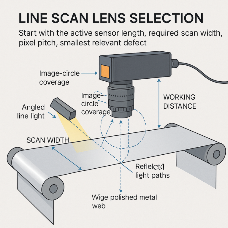
Line Scan Lens Selection for Large Sensors and Reflective Parts
10 min read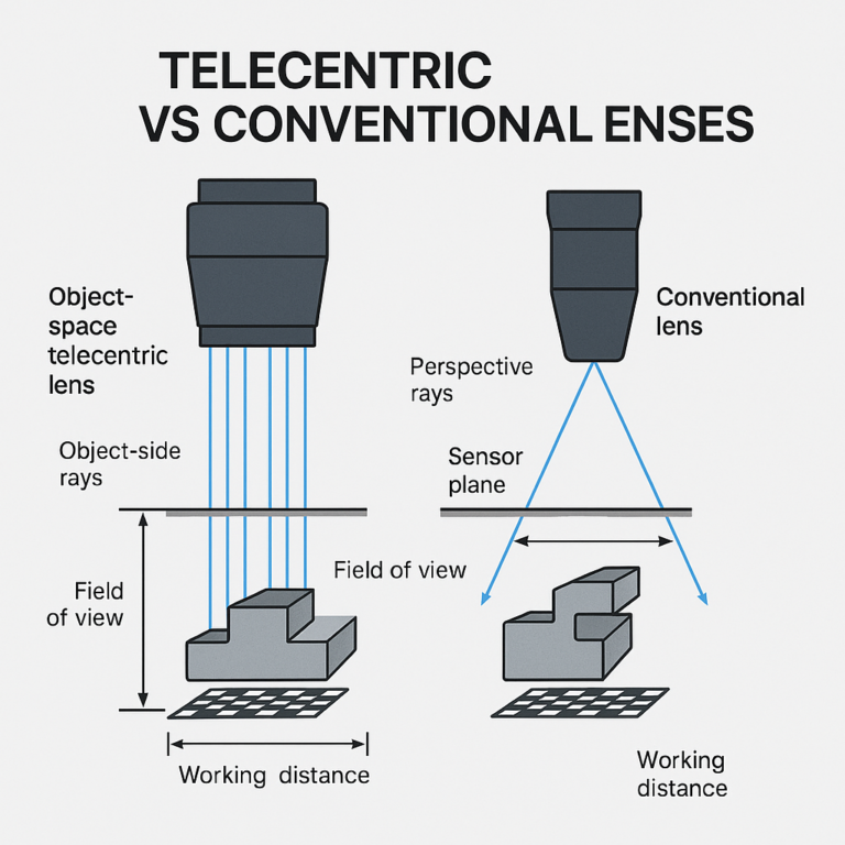
Telecentric vs Conventional Lenses: Cost, Accuracy, and Calibration
10 min read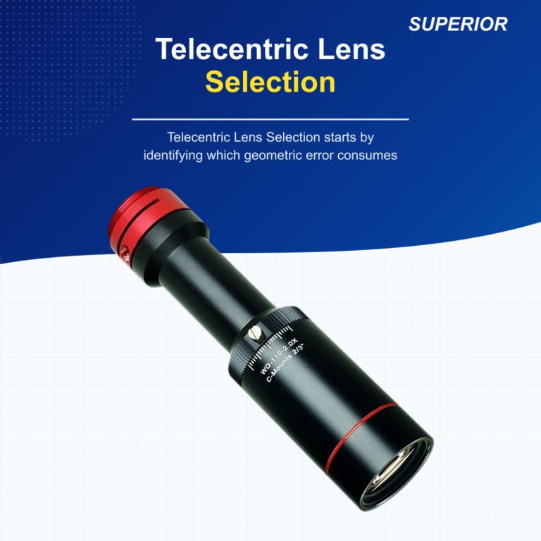
Telecentric Lens Selection for Dimensional Metrology Systems
12 min readAbout SUPERIOR OPTICS
SUPERIOR OPTICS specializes in CCTV lenses, machine vision optics, and custom optical solutions for security, industrial imaging, and specialty applications. We also provide professional lens selection and application support.