


Lens Mount Selection Guide: C-Mount, F-Mount, M42, M58, and More
Compare seven lens-interface families by flange distance, sensor coverage, rear clearance, retention, repeatability and adaptation risk before committing an OEM camera design.
Key Takeaways
This Lens Mount Selection Guide helps buyers eliminate mechanically or optically unsuitable interfaces before committing to detailed lens and camera validation.
- Treat the mount designation as a starting point: verify thread or bayonet geometry, reference plane, tolerance and locking features on both drawings.
- Match flange distance before evaluating focus travel; an adapter cannot always compensate when the destination camera register is too long.
- Check sensor coverage and rear-element clearance separately because a lens can cover the sensor yet still collide with the camera.
- Use larger interfaces only when optical clearance, load support or platform requirements justify their added envelope and sourcing constraints.
- Standardization reduces parts only when every camera platform shares a documented optical, mechanical and environmental interface envelope.
The Short Answer
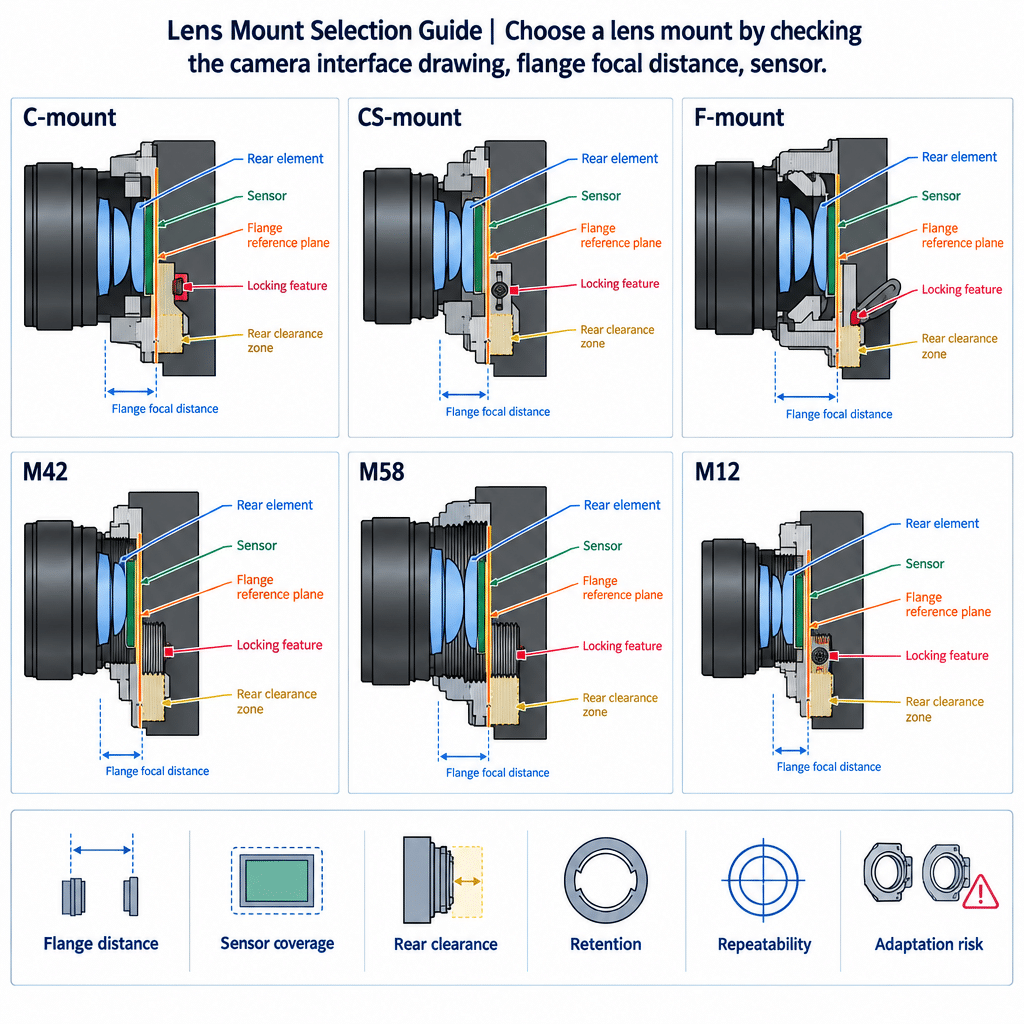
Choose a lens mount by checking the camera interface drawing, flange focal distance, sensor format, lens image circle, rear-element envelope and available focus adjustment. Then assess retention, vibration exposure, sealing and field-replacement needs. C-mount suits many compact industrial cameras; CS and M12 address shorter or smaller packages. F-mount supports larger-format platforms, while M42 and M58 require careful verification because the diameter name alone does not define pitch, register or shoulder geometry. Final approval should be based on controlled drawings, not the mount label.
A mount is both a mechanical joint and part of the optical stack. A lens may screw onto a camera yet fail to focus, vignette the sensor, strike an internal component or move under cable and machine vibration. The table narrows the candidates; it does not replace dimensional review.
Machine Vision Lens Mount Comparison Table
| Mount type | Integration profile | Flange-distance issue | Sensor/image-circle issue | Optical clearance | Rigidity and vibration | Repeatability | Sealing | Adapter flexibility | Best fit | Checks before release |
|---|---|---|---|---|---|---|---|---|---|---|
| C-mount | Compact threaded interface | Defined 17.526 mm register | Verify lens coverage for the exact sensor | Check rear projection and thread depth | Adequacy depends on lens mass and locking | Shoulder condition and focus lock matter | Usually requires system-level sealing | Broad ecosystem; C-to-CS adaptation is possible | General industrial and security imaging | 1-32 thread, register, coverage, lock |
| F-mount | Larger bayonet interface | Defined 46.5 mm register | Often considered for larger sensors | More interface room, but camera throat still governs | Evaluate bayonet play and support for heavy optics | Bayonet condition and rotational seating matter | Depends on camera and lens implementation | Useful where the camera already supports F-mount | Larger-format area- or line-scan systems | Bayonet version, register, throat, support |
| M42 | Large threaded family | Not universal from the name alone | Verify image circle and usable aperture | More nominal diameter than C-mount | Thread engagement can aid retention; validate loads | Shoulder and thread tolerances govern seating | Design-dependent | Good only across matching variants | Larger industrial optics and custom assemblies | Pitch, register, shoulder, rear envelope |
| M58 | Large threaded/custom family | Obtain the specified register | Validate against sensor diagonal | Potentially generous, not guaranteed | Validate barrel mass, engagement and camera structure | Controlled drawings are essential | Design-dependent | Limited if implementations differ | Large rear elements or application-specific optics | Pitch, datum, aperture, support, lock |
| CS-mount | Compact C-thread derivative | Shorter register than C-mount | Verify coverage independently | Adapter and rear-element clearance are sensitive | Best assessed with the installed lens | Spacer control affects focus | System-level provision | Many C lenses work with the correct spacer | Compact security and industrial cameras | Register, spacer, thread depth, collision |
| M12/S-mount | Board-level threaded interface | Camera and lens stack require validation | Coverage can constrain sensor choice | Tight rear and board clearance | Small package; locking method is application-specific | Adhesive or lock method affects service | Enclosure normally supplies sealing | Adapters add stack-up and alignment risk | Compact modules and embedded cameras | M12 × 0.5 interface, coverage, lock, board clearance |
| Custom | Interface tailored to the optical stack | Set by the controlled design | Can be sized around the selected sensor | Designed around rear optics and obstructions | Can incorporate dedicated support | Datums and assembly controls can be optimized | Can integrate seals | Lowest portability unless an adapter strategy is designed | High-volume or constrained OEM systems | Full interface-control drawing and validation plan |
Final compatibility requires the camera drawing, lens drawing, sensor format, rear-element geometry and environmental requirements. Qualitative entries are engineering screening criteria, not universal performance ratings.
How to Choose a Lens Mount for an OEM Camera System
Use this Lens Mount Selection Guide as an elimination sequence rather than starting with brand availability.
- Freeze the camera-side interface. Record thread or bayonet type, pitch, flange reference, permitted protrusion, clear aperture and surrounding obstructions.
- Check the optical register. Flange focal distance is measured from the mount reference plane to the sensor. C-mount uses a 17.526 mm register and a 1-32 thread; F-mount uses 46.5 mm, according to the machine-vision flange-back reference.
- Match sensor and lens. Image circle addresses coverage, while pixel size and lens performance affect usable detail. Review these as separate lens sensor matching requirements.
- Run a collision check. Model the rear element, lens thread, adapter, filters, shutter and camera baffles across the full focus range.
- Define retention and access. State whether focus and iris must lock, whether tools can reach the lock, and whether technicians can replace a lens without disturbing adjacent equipment.
A useful tolerance question is not simply “does it focus?” It is “does every allowed camera, adapter and lens stack retain the required focus margin?” That requires supplier tolerances; nominal flange distances alone cannot answer it.
Machine Vision Lens Mount Comparison: C-Mount, F-Mount, M42, M58, and More
C-mount, CS-mount and M12
C-mount remains common on industrial cameras, combining a compact threaded interface with a defined register. CS uses the same nominal thread family but a shorter register. A C-mount lens can be installed on a CS camera with the appropriate 5 mm spacing ring, while a CS lens on a C camera generally cannot reach its required position, as explained in this C-, CS- and F-mount compatibility guide.
Rear-thread length can still create a collision. For smaller packages, compare M12, C-mount, and CS-mount interfaces against board clearance, sensor coverage and service requirements.
F-mount, M42 and M58
An F-Mount lens uses a bayonet rather than a threaded C interface. Its larger interface is used on some large-sensor industrial cameras, but the bayonet version, rotational seating, camera throat and support for a heavy lens all need confirmation.
“M42” is incomplete as a procurement specification. M42 × 1 and T2’s M42 × 0.75 threads are not interchangeable. An M42 lens mount drawing must therefore identify pitch, register, seating shoulder and rear projection.
The same caution applies more strongly to an M58 lens mount: no verified universal M58 geometry was available for this article. Treat M58 as a diameter family or supplier-specific interface until the pitch, tolerance class, datum, clear aperture and flange position are documented.
Mechanical Factors That Decide Compatibility
Shoulder seating: A threaded lens that stops on thread interference rather than its intended shoulder can shift focus and optical alignment. Define the seating datum and allowable gap.
Rear clearance: Rear elements may project into the camera. Wide-angle designs and adapters are particularly sensitive to internal baffles or filters. A sectioned CAD check is more reliable than comparing mount diameters.
Rigidity: Interface diameter alone does not prove vibration performance. Lens mass, center of gravity, thread engagement, bayonet clearance, camera-wall stiffness and external supports form one load path. The design treatment of machine vision lens mounts, alignment, and barrels should therefore be reviewed as a system.
Installation repeatability: For a replaceable lens, identify which surfaces restore axial position, centering and rotation. Locking rings preserve adjustability but add stack-up; set screws can mark threads or apply side load; dedicated clamps can improve control but consume envelope.
Environment: A mount label does not establish ingress protection or thermal stability. Seals, lubricant, material expansion, shock loads and focus-lock strategy belong in the camera-level reliability specification.
When a C-Mount Lens Is the Right Choice
Choose a C-Mount lens when the camera provides the matching interface, the sensor fits the lens image circle, rear geometry clears the camera and the installed mass can be retained reliably. Its established industrial use and compact package make it a practical starting point when reviewing machine vision lens options.
Do not select it from sensor format alone. Higher pixel counts may expose lens-performance limitations, while a physically larger sensor may vignette even if the lens threads on. Adapters, spacers and locking rings also consume focus travel and can move the lens farther from the camera support structure.
When F-Mount, M42 or M58 Is the Better Trade
F-mount is a defensible choice when the camera natively supports it and the required lens family, sensor coverage or optical assembly calls for the larger interface. A bayonet can speed replacement, but release features and rotational repeatability must suit the application.
M42 is useful when a threaded interface and more clearance than C-mount are needed. It is not a single interoperable standard unless pitch and flange geometry are fixed. M58 can accommodate designs with larger rear elements or custom barrels, but that is an engineering possibility, not a universal guarantee.
The buyer consequence is portability. A larger or supplier-specific mount may solve clearance and load problems while reducing the number of compatible cameras and stocked lenses. Price comparison should therefore include adapters, support brackets, validation effort and field spares—not only the lens.
Standardizing Mounts Without Creating Compatibility Gaps
Start with the worst-case sensor diagonal, rear-element envelope, lens mass, focus tolerance and environmental load across the planned camera family. Then divide configurations into native-mount and adapter-dependent groups.
A useful interface-control specification records:
- mount type, pitch or bayonet variant and tolerance;
- flange datum and permitted axial/runout error;
- clear aperture and prohibited rear-volume envelope;
- lens mass and center-of-gravity limits;
- locking, torque and anti-rotation provisions;
- sealing surfaces and temperature range;
- approved adapters and inspection method;
- field replacement and re-focus procedure.
Standardization is false economy if one platform needs an undocumented spacer or if a lens clears one camera but strikes another. Procurement should track each validated camera–adapter–lens combination as a configuration, not assume family-wide interchangeability.
Lens Mount Selection Checklist for OEM Buyers and Integrators
- Obtain controlled camera and lens interface drawings.
- Record sensor dimensions, cover-glass stack and active-area position.
- Verify image circle, focal length, working distance and target field of view.
- Compare flange reference positions and cumulative axial tolerances.
- Sweep rear-element and barrel geometry through focus and iris travel.
- Define lens mass, orientation, shock, vibration and cable loads.
- Choose focus, iris and mount locking methods with service access in mind.
- Document seals, materials and operating temperature requirements.
- Identify native and adapter-dependent configurations separately.
- Approve incoming inspection and field-replacement criteria before release.
When a Custom Optical Assembly Is a Better Fit
Repeated spacers, stacked adapters, external supports or inaccessible locks indicate that the standard interface may be transferring risk rather than reducing it. The Lens Mount Selection Guide reaches its limit when the camera envelope, optics and retention cannot be specified independently.
A request for custom optical lens assemblies should include the camera drawing, sensor format, field of view, working distance, spectral range, rear-clearance model, environmental loads, focus strategy, expected service method and preferred mount family. Future options can be preserved with a replaceable camera-side adapter or a controlled common datum.
For a compatibility review, provide those inputs plus the intended lens mass and any approved adapter. The output should be a documented fit assessment and a list of unresolved tolerances—not a mount recommendation based only on diameter.
Frequently Asked Questions
Can a lens adapter preserve infinity focus between two different mount systems?
Yes, but only when the source lens register and destination camera geometry leave enough room for the adapter while placing the lens at its required flange distance. If the camera’s native register is too long, a simple mechanical adapter may prevent infinity focus. Rear-element clearance must also be checked.
What information should an OEM provide to verify lens-to-camera mechanical compatibility?
Provide controlled drawings for the lens and camera, mount designation and pitch, flange datum, sensor format, rear-element envelope, clear aperture, focus travel, lens mass and environmental loads. Include adapters, filters and shutters in the stack because any one of them can alter spacing or create a collision.
How do locking screws, set screws and retaining rings affect lens replacement in the field?
They change both repeatability and service procedure. A locking ring can preserve threaded adjustment but adds another seating surface. A set screw may apply side load or mark a thread. Document tool access, torque, replacement sequence and whether focus or optical alignment must be reverified after service.
When should a camera platform use a dedicated mount instead of an adapter?
Use a dedicated mount when adapter stack-up consumes focus margin, reduces clear aperture, creates rear-element interference or cannot support the installed lens under specified loads. It is also preferable when production repeatability, sealing or rapid field replacement outweighs the sourcing flexibility offered by an adapter-based configuration.
What should be documented in a lens mount interface control specification?
Document the interface variant, thread pitch or bayonet geometry, flange reference, tolerances, clear aperture, prohibited rear volume, seating shoulder, locking method, lens-load limits and sealing surfaces. Add approved adapters, inspection datums and replacement procedures so purchasing, assembly and service teams evaluate the same controlled configuration.
Topics
Related Articles
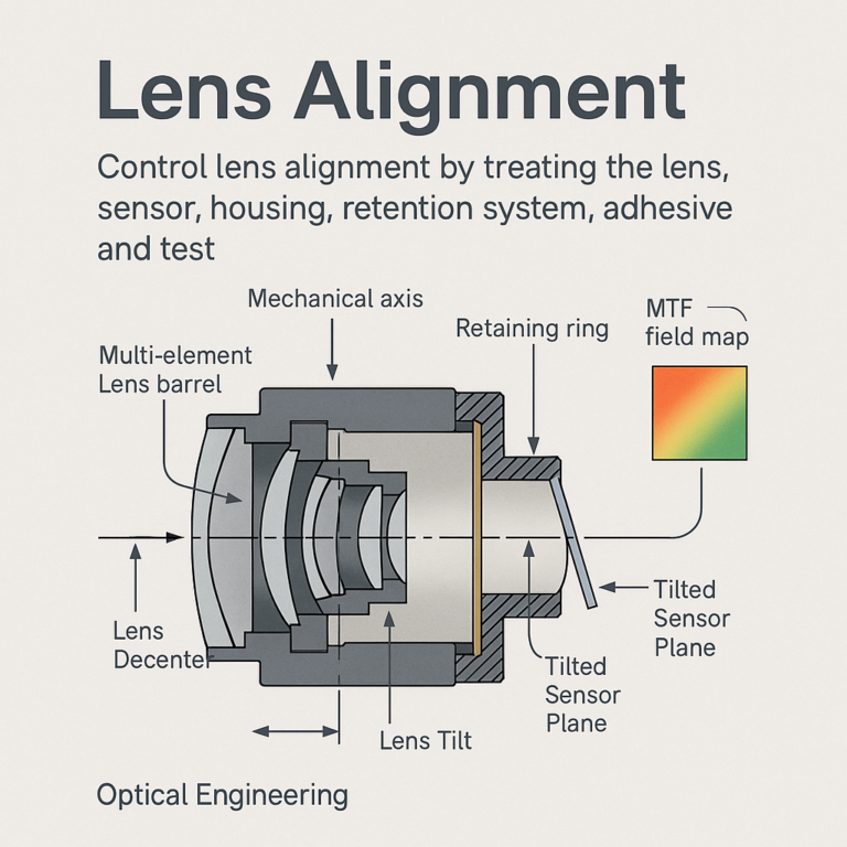
How to Control Lens Alignment, Tilt, Decenter, and MTF Degradation
11 min read
Machine Vision Lens RFQ Checklist for OEM Production Programs
11 min read
C Mount CCTV Lens for Effective and Adaptable Coverage with Low Cost
9 min readAbout SUPERIOR OPTICS
SUPERIOR OPTICS specializes in CCTV lenses, machine vision optics, and custom optical solutions for security, industrial imaging, and specialty applications. We also provide professional lens selection and application support.