
Lens Distortion vs Parallax: What Inspection Buyers Must Know
A diagnostic guide to separating geometric distortion, parallax, perspective error, and TV distortion before selecting calibration, mechanical changes, or telecentric optics.
Key Takeaways
The Lens Distortion vs Parallax decision starts by identifying whether error follows image position, object depth, viewing angle, or mechanical variation.
- Use calibration for stable, repeatable lens-mapping error—not for uncontrolled changes in part height or camera pose.
- Test parallax by changing object height while holding its lateral position and the camera mount fixed.
- Treat TV distortion and geometric distortion as different specification measures rather than interchangeable accuracy figures.
- Improve fixturing, mounting, triggering, and motion control before attributing cycle-to-cycle variation to the lens.
- Evaluate telecentric optics when magnification must remain stable across the permitted object-depth range.
The Short Answer
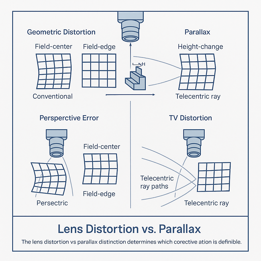
The Lens Distortion vs Parallax distinction determines which corrective action is defensible. Geometric distortion is a repeatable mapping error tied mainly to image position and may be modeled through calibration. Parallax is an apparent feature shift caused by viewpoint and object depth. Perspective error changes apparent scale as camera-to-object distance changes. TV distortion is a separate lens specification and not a complete dimensional-accuracy diagnosis. Use calibration for stable mapping error, geometry or mechanical control for changing pose, and telecentric optics when depth-driven magnification variation remains unacceptable.
Define the Four Errors Buyers Commonly Confuse
What is geometric distortion?
Geometric distortion changes where image points are mapped across the field. A straight reference can bow near the edge even though the target itself is straight. The pattern is generally useful diagnostically when it repeats at the same field positions under fixed imaging conditions.
This differs from blur. A feature can remain sharply focused yet be mapped to the wrong image coordinate. For measurement, the relevant question is not merely whether the data sheet says “low distortion,” but whether residual mapping error stays inside the application’s error budget after calibration, if calibration is planned.
What is parallax?
Parallax is an apparent positional shift caused by viewpoint and depth. If a raised feature is viewed off-axis, changing its height can move its image laterally even when its position on the fixture has not changed.
The lens is not necessarily defective. The system is observing the feature along a different line of sight. Camera angle, object depth and placement repeatability therefore matter as much as the nominal lens specification.
What is perspective error?
A conventional lens forms a perspective image: features at different camera-to-object distances can appear at different scales. A dimension calibrated on one plane may consequently read differently when the same feature is presented on another plane.
Parallax emphasizes apparent position; perspective error emphasizes apparent size or shape. Both are depth-sensitive and can occur together.
What is TV distortion?
TV distortion and geometric lens distortion are different measures. Schneider-Kreuznach cautions that lens data sheets are not standardized across vendors and that TV distortion should not be compared directly with geometric distortion.
Buyer inference: a TV distortion figure alone cannot establish dimensional accuracy. Ask what reference geometry, image height and calculation method produced the value, then validate the lens against the actual sensor, field and measurement task.
How to Distinguish Lens Distortion From Parallax in an Inspection Image
A reliable Lens Distortion vs Parallax diagnosis changes one variable at a time. Start with a stable artifact and locked camera. Capture the target at field center and near the field edge. If the error follows field position and repeats, geometric distortion is a likely contributor.
Next, keep lateral placement fixed and change target height. A lateral feature shift indicates depth-sensitive viewing geometry. If measured width or diameter changes with height, perspective-driven magnification is present. Those tests should be repeated only after focus, illumination, exposure and edge-detection settings are held constant.
Random cycle-to-cycle variation points elsewhere. Repeat captures of an immobile artifact separate optical mapping from fixture movement, camera vibration, changing part orientation or acquisition timing. In line-scan systems, inconsistent motion can stretch or compress the reconstructed image; line scan imaging timing and encoder feedback therefore belong in the diagnosis before a lens is rejected.
Use calibration for repeatable mapping error; revise geometry or mechanics for changing viewpoint and placement; evaluate telecentric optics when depth-driven scale variation remains outside tolerance.
Diagnostic Table: Symptom, Likely Cause, and Correct Remedy
| Observed symptom | Likely issue | Confirmation test | Preferred remedy | Telecentric decision |
|---|---|---|---|---|
| Straight references bow consistently near field edges | Geometric distortion | Move a known straight target through several field positions | Calibrate the stable mapping or select a lower-distortion lens | Not justified by distortion alone |
| A feature shifts laterally when part height changes | Parallax | Raise or lower the fixed target without changing lateral placement | Reduce viewing angle, revise camera position or control height | Consider when depth variation cannot be removed |
| Apparent feature size changes with object distance | Perspective error | Measure the same artifact at controlled height positions | Increase working distance, constrain height or use telecentric optics | Consider when scale stability is required across depth |
| Calculated and observed field widths disagree | Specification or geometry mismatch | Verify sensor format, working distance, image circle and calculation assumptions | Rebuild the optical geometry and clarify the distortion metric | Only if depth sensitivity is also a requirement |
| Measurements drift without a stable field pattern | Mechanical or acquisition variation | Repeat a fixed artifact, then vary one mechanical condition at a time | Improve fixture, mount, motion, trigger or process control | Evaluate only after mechanical variation is quantified |
The table identifies probable causes, not proof. Edge localization, illumination, sensor sampling and algorithm settings can also affect the reported measurement, so optical changes should be evaluated inside the complete error budget.
When Camera Calibration Software Can Correct Geometric Distortion
Camera calibration software can model a repeatable relationship between object coordinates and image coordinates. It is appropriate when the lens, sensor, focus, aperture, working distance, calibration target and fixture remain controlled. Production measurements must also remain within the validated calibration region.
Calibration does not make a perspective lens depth-invariant. A map established on one plane cannot, by itself, guarantee the same magnification on another plane. Nor can a static correction compensate reliably for a camera mount that moves, a refocused lens or uncontrolled part pose.
A useful acceptance test compares residual measurement error at field center and edge, across the permitted part positions and after expected maintenance interventions. The buyer should define the recalibration trigger rather than treating calibration as a one-time software checkbox.
When Camera Geometry and Mechanical Control Matter More Than the Lens
Focal length, sensor coverage, field of view and working distance form one geometry. Changing one constraint can alter package clearance, viewing angle and sampling at the object. Candidate machine vision lenses for industrial inspection should therefore be compared at the intended sensor format and working distance, not by an isolated distortion value.
Part-height variation is especially costly when the measurement plane is not controlled. Better nesting, datum contact or orientation control may remove more uncertainty than a lens upgrade. Increasing working distance can reduce angular sensitivity in some layouts, but it may require another focal length or a larger mechanical envelope. That is an engineering trade-off, not a universal remedy.
Mount rigidity also matters. A moving camera changes the coordinate relationship that calibration assumes. Area-scan systems expose a frame at once, while line-scan systems build images through motion; the appropriate machine vision inspection system architecture changes which mounting, synchronization and motion errors require validation.
When Telecentric Optics Are the Right Investment
Object-space telecentric lenses maintain more consistent magnification as object distance changes within their usable inspection range. They reduce perspective and parallax error relative to conventional lenses, but low perspective error and low geometric distortion remain separate requirements. SUPERIOR’s technical comparison of telecentric optics, calibration, and measurement accuracy also notes the usual trade-offs: telecentric systems tend to require more cost and packaging space.
The investment is easier to defend when dimensional tolerance is tight, object height varies within a known range, features occupy different planes, or fixture control cannot hold every measurement surface near one calibration plane. The clear aperture, field requirement, working distance, lighting access and mechanical envelope still need to fit the machine.
A conventional lens remains credible when parts stay near a controlled plane, calibration is stable, residual error passes the application test and the assembly must remain compact or cost-constrained. Telecentricity should solve a measured depth-sensitivity problem—not serve as a substitute for diagnosing loose fixtures or unstable acquisition.
A Buyer Checklist Before Selecting a Lens or Optical Assembly
A Lens Distortion vs Parallax review should leave a supplier with testable boundary conditions:
- Set the error budget. State the feature tolerance, required field, measurement plane and maximum allowable optical contribution.
- Document geometry. Provide sensor format, pixel count, field of view, working-distance range, camera angle and mechanical envelope.
- Quantify depth. Record nominal feature height, allowed height variation and whether multiple planes must be measured in one image.
- Describe repeatability. Include fixture datums, placement variation, camera-mount stability, motion and trigger method.
- Test the field. Compare known artifacts at center, edge and permitted height positions rather than approving only a central image.
- Define calibration control. Identify what can change in production and what event requires recalibration.
- Choose the lowest-risk remedy. Compare software correction, geometry changes, better fixturing, a lower-distortion conventional lens and telecentric optics against the same acceptance test.
For lens-selection guidance, provide the inspection geometry, tolerance, part-depth range, sensor details and working-distance limits. SUPERIOR can use those constraints to assess industrial optical lens and custom assembly options before the design is committed to an unsuitable calibration or optical approach.
Frequently Asked Questions
Can lens distortion be corrected completely with camera calibration software?
Not in every case. Calibration can correct a stable, modeled mapping error when the camera, lens, focus, working distance, fixture and calibration plane remain controlled. It cannot make magnification independent of object depth or compensate reliably for a camera or part pose that changes after calibration.
Does a telecentric lens eliminate all inspection measurement error?
No. Telecentric optics reduce depth-driven magnification change and perspective or parallax error within their usable range. Measurement can still be affected by geometric distortion, sensor sampling, focus, illumination, edge detection, mounting, fixture variation and calibration quality. Each contribution must be checked against the system error budget.
Why does an object appear to move in the image when its height changes?
The apparent movement is usually parallax. With an off-axis or perspective view, raising the feature changes the line of sight between that feature and the camera, producing a lateral image shift. Confirm it by changing height while keeping the fixture, camera and lateral feature position fixed.
Is TV distortion a reliable specification for dimensional machine vision inspection?
Not by itself. TV distortion and geometric distortion use different measures, and vendor data-sheet methods may differ. Ask how the value was calculated, then test image-coordinate or dimensional error over the required sensor field, working distance and object-depth range. The inspection tolerance must govern acceptance.
How much part-height variation can a conventional lens tolerate in machine vision inspection?
There is no universal allowable value. Tolerance depends on lens geometry, working distance, feature location, sensor sampling, calibration plane and the permitted measurement error. Test the selected lens at the minimum and maximum production heights. If scale variation exceeds the error budget, improve height control or evaluate telecentric optics.
Topics
About SUPERIOR OPTICS
SUPERIOR OPTICS specializes in CCTV lenses, machine vision optics, and custom optical solutions for security, industrial imaging, and specialty applications. We also provide professional lens selection and application support.