


Opto-Mechanical Design
Review how the barrel, retaining elements and mounting interfaces hold the optics in position.
Explore Opto-Mechanical DesignSUPERIOR OPTICS / CAPABILITIES
Optical design turns an imaging requirement into a lens configuration that can be modeled and tested. At SUPERIOR Optics, optical system design starts with the sensor, field of view, working distance and wavelength band. These inputs guide trade-offs in resolution, distortion, illumination and lens size before a design moves to prototype review.
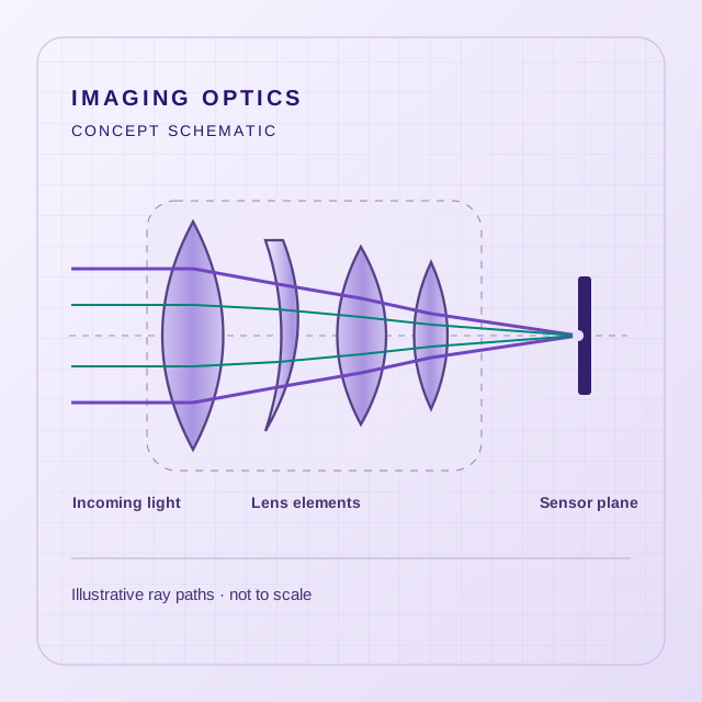
We review sensor coverage, field of view and image quality together to see whether the lens can meet your imaging targets within the available space. A tolerance review then helps identify which dimensions or assembly variations could affect performance.
Review sensor dimensions, working distance and the area that must appear in the image. This establishes the required coverage and helps narrow the optical configuration.
Review MTF, distortion and relative illumination under agreed conditions. Compare the center and edge of the field before deciding which compromises are acceptable.
Review how material, surface, spacing and alignment variations may affect performance. Use the results to identify where tighter tolerances or a design change may be needed.
Send the sensor, field of view, working distance, wavelength band and packaging limits you know, and flag any targets still open. Before work starts, agree on the review criteria, reports or drawings to be delivered, prototype scope and access to design files.
| Review item | Inputs / scope | Review output |
|---|---|---|
| System inputs | Sensor dimensions, pixel pitch, field of view and working distance | Requirements baseline with assumptions and open questions. |
| Performance model | Wavelengths, aperture, MTF, distortion and illumination targets | Design analysis at specified conditions and field points. |
| Mechanical constraints | Envelope, mount, filter stack, back clearance and datums | Optical-mechanical interface requirements. |
| Tolerance analysis | Material, element, alignment and assembly variations | Sensitivity review and a proposed tolerance allocation. |
| Deliverables and rights | Reports, drawings, prototype support and design-data access | Contract-defined deliverables, review gates and ownership. |
Compare fixed focal length, telecentric and line scan lenses by the questions that shape each design: sensor coverage, imaging geometry, image quality and integration. Use the table to plan what to check on a sample; specifications and modification options depend on the model and project.
| Design consideration | Fixed Focal Length | Telecentric | Line Scan |
|---|---|---|---|
| Sensor and coverage | Active sensor dimensions, pixel pitch and image circle | Area-sensor format, object field and magnification | Active line length, pixel pitch and image coverage |
| Imaging geometry | Field of view, working distance and object depth | Object field, working distance and measurement depth | Scan width, working distance and magnification |
| Image performance | MTF across the field, distortion and relative illumination | Distortion, telecentricity and contrast across the measuring field | MTF and illumination uniformity across the sensor line |
| Integration and modification | Review focal length, aperture, mount and back clearance | Review magnification, working distance and lighting clearance | Review mount, back clearance and alignment with the scan line |
| Sample verification | Check center and edge image quality at the intended distance | Check measured dimensions as object height changes | Check detail and brightness across the scan width |
Start with what the camera must capture or measure. A compact camera, an inspection station and a system operating across several wavelengths have different priorities for sensor fit, the smallest visible detail and focus across the required bands.
Review the sensor stack, chief ray angle and available space around the sensor. Confirm edge coverage before committing to a compact configuration.
Start with the smallest feature to detect, then define field size, working distance and lighting. Use those conditions to set the contrast and distortion targets.
Specify the operating bands and illumination. Review material transmission, coating needs and focus across the wavelengths that matter to the application.
This workflow shows what to agree on before each stage of an optical design project, from defining imaging requirements to reviewing prototype results. It also sets out what to document before design approval and handoff to production.
Confirm the sensor, imaging geometry, operating conditions and acceptance targets. Record which requirements are fixed and which can be traded off.
Compare candidate configurations, identify optical and mechanical constraints, and agree on deliverables, ownership and the prototype scope.
Compare the optical model with prototype results at the agreed field points, distances, apertures and wavelengths. Record deviations and open issues.
Confirm the approved revision, verification records, outstanding risks and change approval process. Discuss volume production separately with the OEM / ODM team.
An optical model predicts how a lens should perform under defined conditions. A prototype shows how the built lens performs under those conditions. Before the build, agree on what to measure, how to measure it, and what counts as a pass.
Select the measurements that matter for the application, such as image sharpness at the center and edges, distortion, or relative illumination. Agree on the acceptance limits and test conditions before the prototype is built.
Record the sample revision and test setup, including the sensor, aperture, wavelength, field position, and test distance where relevant. Compare the measured results with the optical model under matching conditions, then check them against the agreed acceptance limits.
If results differ from predictions or fall outside the agreed limits, check the measurement setup, component tolerances, and assembly alignment before changing the design. Record what passed, what needs retesting, and which issues remain open.
BUYER QUESTIONS
Clarify what to submit, what the design scope covers and how results will be reviewed.
Provide sensor details, field of view, working distance, wavelength band, image-quality targets, and mechanical limits. Include quantity and cost expectations where available. A requirements review can identify missing inputs before detailed optical work begins.
Only when it is included in the agreed scope. Separate optical analysis, mechanical design, prototype fabrication, assembly, testing, and production support in the proposal so responsibilities and acceptance criteria remain clear.
A nominal design assumes ideal parameters. Tolerance analysis examines how realistic variations may affect performance and helps allocate limits to elements and assembly. It supports manufacturing decisions but still requires validated inputs and physical testing.
That depends on the contract and licensed rights. Define the file formats, reports, drawings, prescription access, confidentiality, ownership, and permitted reuse before commissioning the service.
PROJECT INQUIRY
Need custom lens design or a review of an existing optical system? Send your sensor model, field of view, working distance, wavelength band and packaging limits. If you have them, include performance targets, expected quantities and the design files or test reports you need.
Include a model number or the information currently available:
You do not need a complete optical specification to start. Send the information currently available, along with your delivery destination and preferred schedule.