


Optical Design Services
Define the imaging prescription, target performance and design verification plan.
Explore Optical Design ServicesSUPERIOR OPTICS / CAPABILITIES
Opto-Mechanical Design defines how lens elements are positioned, secured, and aligned within a lens barrel or camera assembly. Reviewing mounting datums, tolerance stack-up, assembly access, and operating conditions together helps identify which mechanical features must be controlled and which checks should be performed on the prototype.
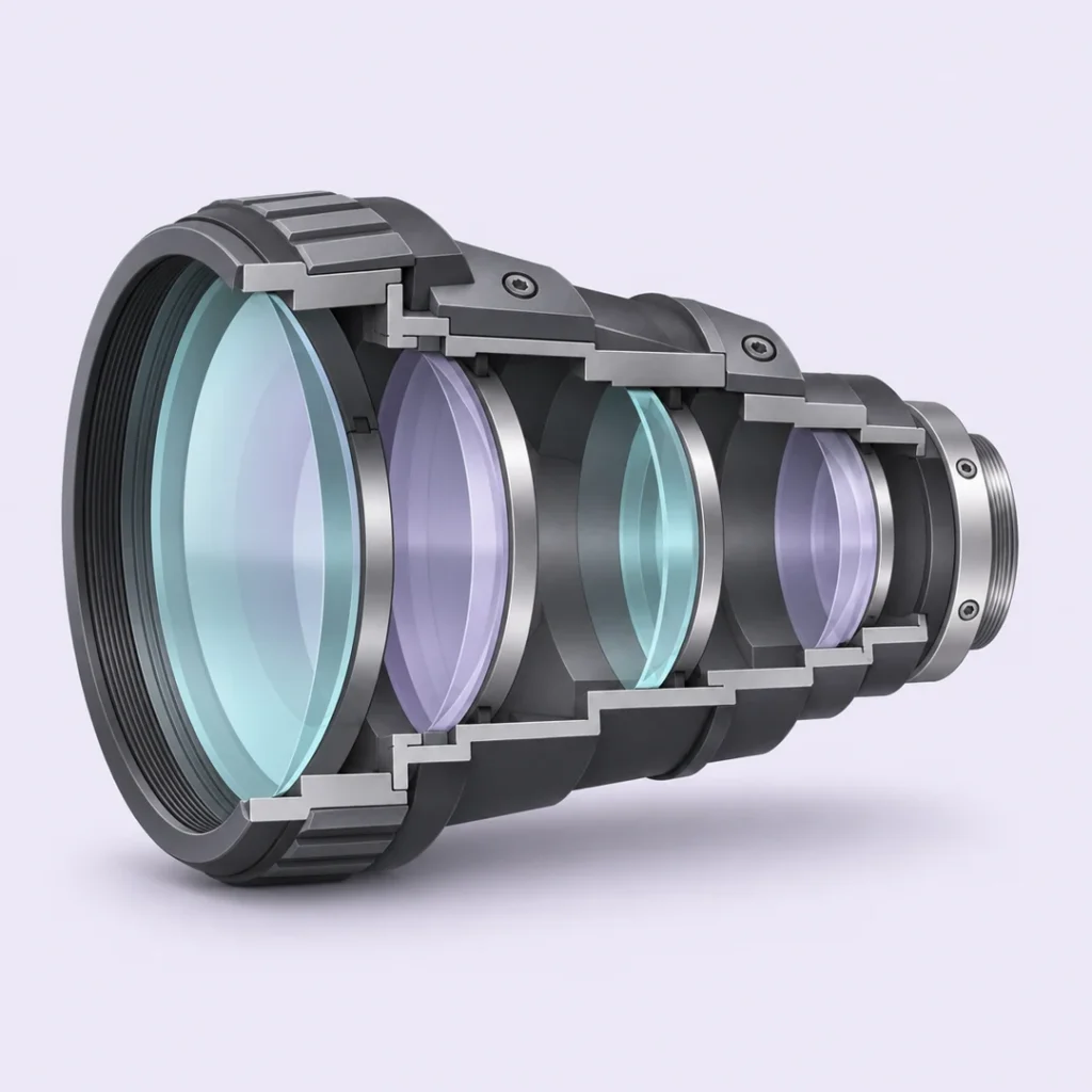
Opto-Mechanical Design translates the optical layout into a lens assembly that can be built and adjusted. Define how the barrel locates each element, how the retainers hold it without introducing stress, and which checks to repeat after focus is locked.
Identify the optical axis, axial seating surfaces and mounting references. Mark which dimensions control spacing, centering and tilt.
Review the retainer, contact surfaces and assembly sequence. Flag preload, distortion and material expansion where they could change alignment.
Identify where focus or alignment must be set, locked and checked again. Allow access for fixtures and measurement before closing the barrel.
Review mechanical decisions against the optical error budget, assembly process and operating environment. The examples below identify design questions to resolve before dimensions or acceptance limits are fixed.
| Design decision | What can change | What to review |
|---|---|---|
| Lens seat and mounting datums | An off-center seat or tilted mounting face can move the optical axis relative to the sensor. | Define the locating axis and mounting face, then check how both transfer to the assembly fixture. |
| Spacer stack and focus travel | Variation in axial spacing can shift best focus or consume the available adjustment range. | Budget the stack, identify the most sensitive spacings and reserve enough travel for build variation. |
| Retaining ring and preload | Too little restraint may allow movement; uneven or excessive contact load can distort an element. | Review the contact geometry, load path and tightening sequence. Compare before and after locking where relevant. |
| Housing material and temperature | The barrel, spacers and glass can expand differently, changing fit or focus. | Use the project temperature range and candidate material data to review clearance and focus drift. |
| Internal finish and stray light | A surface that looks dark in visible light may behave differently in the operating band. | Define the band and relevant illumination geometry. Compare candidate finishes using project-specific evidence. |
| Shock, vibration and handling | Disturbance can shift an element or change a locked setting. | Specify the applicable load profile and which fit or image checks must be repeated afterward. |
For an Opto-Mechanical Design review, share the optical layout, sensor position, mounting envelope, and operating conditions. Flag any open requirements so both teams can agree on the drawings, tolerance checks, and prototype verification results needed for the next stage.
| Review item | What to share | Review output |
|---|---|---|
| Interfaces | Optical layout, sensor position, mounting envelope and mating features | Interface drawing and agreed datum scheme |
| Tolerance chain | Sensitivity to spacing, tilt and decenter; candidate part and assembly tolerances | List of critical dimensions and adjustment points |
| Retention and environment | Lens material, housing material, temperature range and handling loads | Retention concept and verification conditions |
| Review package | Drawing revision, assembly sequence and access constraints | Items to verify on the first mechanical build |
Technical reference: If your project drawings use GD&T, refer to ASME Y14.5 — Dimensioning and Tolerancing for guidance on specifying datums and geometric tolerances for lens seats and mounting interfaces.
Use the design review to turn an optical prescription into drawings, assembly checkpoints and a first-build test plan. Agree on the deliverables and acceptance criteria for each project before detailed design.
Record the sensor plane, mechanical envelope, mounting face, clearances and optical performance targets. Identify which features belong to the lens and which belong to the camera.
Review sensitivity to spacing, tilt and decenter. Decide which variation should be controlled by the part drawing, which can be adjusted during assembly and how each feature will be measured.
Check part orientation, fixture access, retention and the sequence for setting and locking focus. Define the configuration, sample quantity and conditions needed to assess the first build.
Compare fit and imaging results with the agreed criteria. Record open risks, corrective changes and the drawing revision to use for the next build.
Use the first build to check fit, adjustment access and whether the critical dimensions can be verified on the assembled unit. Compare the actual condition with the agreed mechanical and optical limits.
Verify that the first build matches the Opto-Mechanical Design drawings. Check that the lens barrel seats fully against the mounting face, clears nearby hardware, and leaves enough access to adjust and lock focus.
Record focus or alignment before and after locking, using the same fixture and measurement conditions. If the reading shifts, compare the change with the agreed limit and check whether tightening moved the lens or changed how it sits in the barrel.
Record what failed, which part or assembly step needs to change, and which drawing revision applies to the next build. Repeat the affected checks on the revised assembly and document the results before approving it for release.
The same mounting question can have different consequences in different cameras. These are illustrative review scenarios, not completed projects or product specifications.
| Application | Typical integration question | Example verification |
|---|---|---|
| Compact M12 or board cameras | Can the barrel and holder fit inside the housing while preserving usable focus travel and rear clearance? | Check seating, sensor-side clearance and focus before and after locking. |
| Machine vision and telecentric lenses | Can the camera mount locate the lens consistently when the system is reassembled or serviced? | Check interface repeatability and the agreed imaging or measurement target after remounting. |
| SWIR imaging | Can the enclosure and barrel control unwanted reflections across the specified operating band? | Review the internal finish in the relevant band and agree on the stray-light test configuration. |
BUYER QUESTIONS
Common Opto-Mechanical Design questions cover lens mount changes, thermal effects, and focus checks after locking.
Optical design defines the imaging prescription and performance targets. Opto-mechanical design locates and holds the optics and gives the assembly team a way to build and verify that prescription.
Share the current drawing and mating envelope. Review the impact on back clearance, focus travel and alignment before committing to a modification.
Include the expected operating range when focus or alignment may change with temperature. Agree on the conditions and any thermal verification required.
Agree on which interface drawings, CAD exchange files, tolerance assumptions, assembly instructions and prototype records are included. Confirm ownership, revisions and acceptance criteria before work starts.
Where retention could change focus or alignment, specify a before-and-after check using the same fixture, distance and focus metric. Set the allowed change for the application.
PROJECT INQUIRY
Send the optical layout, mounting envelope, mechanical drawing and critical alignment requirements.
Include a model number or the information currently available:
You do not need a complete optical specification to start. Send the information currently available, along with your delivery destination and preferred schedule.