Product Family Description
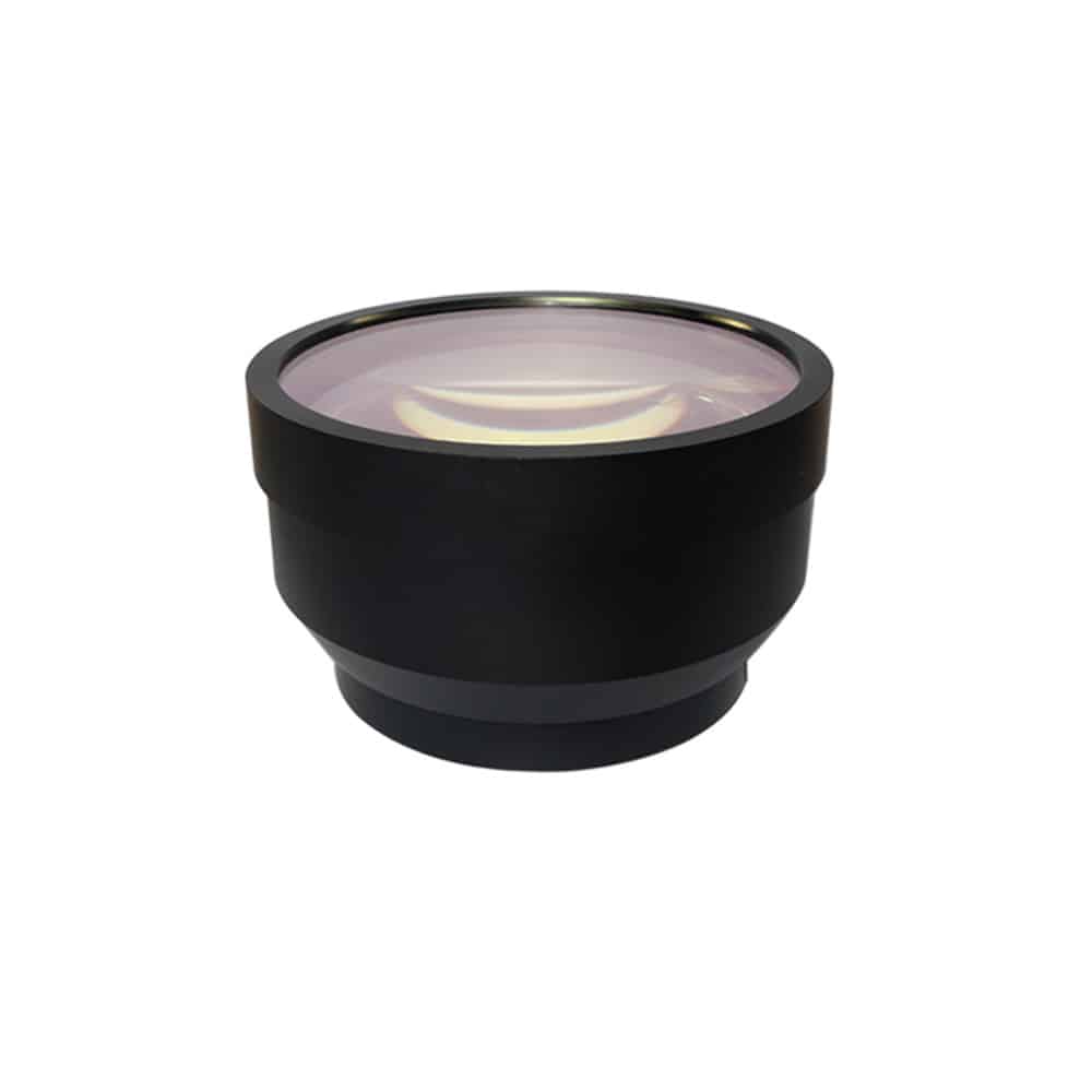
F-Theta Lenses consist of an air-spaced 2- or 3-element design and are available with one of three focal lengths: 100 mm, 160 mm, or 254 mm. The elements are coated with a high efficiency AR coating for a 1064 nm Nd: YAG laser and for a visible alignment laser (refer to the Graphs tab for details). Each housing has a standard M85 x 1.0 or M39 x 1.0 thread for compatibility with most commercial laser marking systems, including ScanLAB, TRUMPF, and Datalogic, as well as a protective glass window that can be easily changed using the instructions provided below. Replacement AR-coated protective windows are also available.
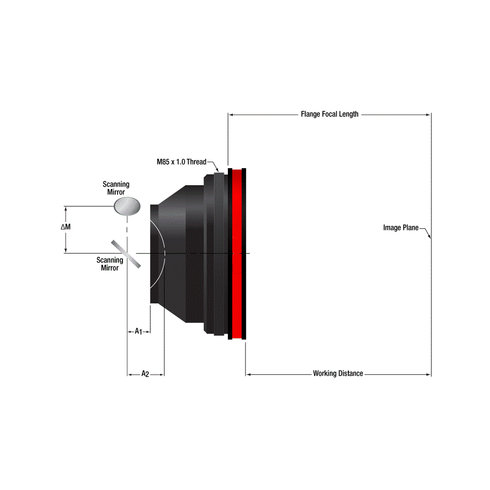
F-theta lenses are the standard lenses for galvo-scanner-based laser marking, engraving, and cutting systems. The diffraction-limited, multiple-element, air-spaced lens design is optimized for a flat field in the image plane and low f-theta distortion. In an f-theta lens, the output beam displacement is equal to f*θ, where θ is the angle of incidence of the input beam (see the diagram above). Thus, the input beam and output beam angular velocities are directly proportional, allowing the scanning mirrors to run at a constant angular velocity, greatly simplifying control electronics. For more details on f-theta lenses, please see the F-Theta Tutorial tab above.
CMANSWIR
- 1064 nm Design Wavelength for Nd:YAG Laser Systems
- Flat Field at the Image Plane
- Large Scan Fields Ranging from 70 mm x 70 mm to 156.7 mm x 156.7 mm
- F-Theta Distortion of <0.1% or <1.3%
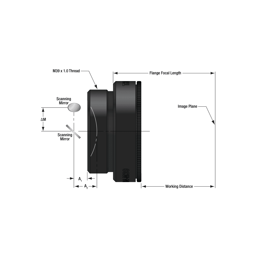
- M85 x 1.0- and M39 x 1.0-Threaded Versions Available
- Air-Spaced Design
- All Optical Elements are AR Coated
- Accessories Available Below:
- Replacement Protective Glass Windows
- Galvo Mirror Mounting Bracket
- Mounting Adapters for 60 mm Cage Systems, Ø2″ Lens Tubes, or Ø3″ Lens Tubes
DATA SHEET
| Model No. | SP-FA6056M60F |
|---|---|
| Effective Focal Length (EFL) | 170±5%mm |
| Scan Angle (Max) | ±28° |
| Scan Length (Max) | 156.4 mm |
| Scan Field (Max) | 110.6 mm x 110.6 mm |
| Beam Diametera | 12 mm |
| Spot Size (Diffraction Limited) | 26 µm |
| F-Theta Distortion (Max) | 0.1% |
| Working Distancea | 182.5 mm |
| Flange Focal Lengtha | 191.7 mm |
| A1a (Typical) | 7.5 mm |
| A2a (Typical) | 12.3 mm |
| ΔMa (Typical) | 20 mm |
| Number of Elements | 3 Plus Protective Window |
| AR Coatingb | 1020 nm – 1080 nm: Ravg < 0.3% (per Surface) 450 nm – 700 nm: Ravg < 1.0% (per Surface) |
| Damage Threshold | 5 J/cm2 (1064 nm, Ø1 mm, 10 ns, 10 Hz) |
| Lens Housing Diameter at Largest Point | Ø90 mm (Ø3.54″) |
| Mounting Threads | M85 x 1.0 |
| Replacement Protective Window Item #c | SP-FTHW75-1064 |