


Machine Vision Lens Testing: MTF, Tolerance, and Reliability
A buyer-focused framework for testing machine vision lenses under representative sensor, aperture, wavelength, working-distance and environmental conditions.
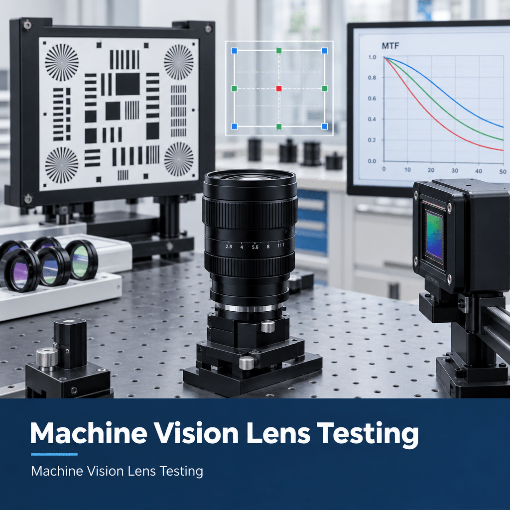
Key Takeaways
Machine Vision Lens Testing is defensible only when the acceptance method represents the production camera, geometry, spectrum and operating state.
- Convert field of view, feature-detection and distortion requirements into measurable limits before issuing a purchase order.
- Evaluate MTF at relevant field positions and orientations, not only at the image center.
- Separate 100% checks, lot-sampled measurements and periodic reliability audits according to failure risk.
- Include measurement uncertainty and fixture variation when making decisions near a specification limit.
- Retain configuration, equipment, lot, result and disposition records so drift can be traced to a product or process change.
The Short Answer
Machine Vision Lens Testing should verify that production lenses meet application-specific optical and mechanical limits under the intended sensor, aperture, wavelength, focus state, object distance and working environment. Incoming inspection commonly covers MTF, effective focal length, field of view, distortion, centering, image-circle coverage and interface integrity. Buyers should assign each characteristic to 100% inspection, lot sampling or periodic audit testing, then document the method, uncertainty, acceptance limit and retest rule. Supplier data remains useful for characterization, but it cannot replace an agreed acceptance method when its test conditions differ from the production system.
What Machine Vision Lens Testing Should Verify at Incoming Inspection
Translate application requirements into measurable acceptance criteria
A practical Machine Vision Lens Testing specification starts with the imaging task. Field of view, smallest relevant feature, sensor format, working distance, illumination band and allowable distortion should become measured characteristics with stated limits. Terms such as “high resolution” or “low distortion” are not enforceable acceptance criteria.
The limit must follow the task. A dimensional measurement system may prioritize low, stable distortion and repeatable edge response. A presence-detection station may tolerate more geometric error but still require enough contrast to separate the target from its background.
Separate supplier characterization data from incoming acceptance data
A design curve, prototype measurement and production-lot result answer different questions. Buyers should establish which data category is being supplied and whether it covers nominal or worst-case units. Supplier characterization can guide selection; incoming data decides whether the delivered lot satisfies the technical agreement.
Define the lens configuration, sensor, aperture, wavelength, and working distance
Record the lens variant, mount, aperture, focus state, filter, spectral band, object distance and sensor used for system tests. MTF comparisons are meaningful only when test conditions match. The machine vision guide to reading MTF curves also distinguishes measured lens MTF from a camera-level slanted-edge result that includes the sensor and processing chain.
Build a Machine Vision Lens Acceptance Testing Plan Before Receiving Production Lots
Set lot definition, sample selection, and traceability requirements
A lot might be tied to a purchase order, assembly run or component batch, but the contract should say which. Samples should be selected without allowing only preferred units to reach inspection. Part number, serial or lot identity, drawing revision and date preserve the link between results and delivered material.
Choose 100% checks, sampled tests, and periodic audit tests
The following table is an engineering template, not a universal standard. Sampling depth should reflect failure consequence, process history, inspection cost and the buyer’s quality system.
Machine Vision Lens Acceptance-Test Table
| Acceptance characteristic | Why it matters | Representative condition | Method or fixture | Sampling approach | Acceptance-limit input | Required record |
|---|---|---|---|---|---|---|
| MTF / resolution | Feature contrast | Sensor, aperture, band, distance, field | Lens bench or controlled camera target | Sampled; 100% if risk requires | Detection or measurement need | Curves, images, focus state |
| Effective focal length | Magnification and coverage | Defined conjugate and wavelength | Calibrated target or optical bench | Lot sample | FOV and magnification budget | Result and setup |
| Field of view | Confirms scene coverage | Actual sensor and working distance | Calibrated object-plane target | Sampled or system-level | Required object dimensions | Edge coordinates |
| Distortion | Controls positional error | Full usable field and reference geometry | Grid or mapped target | Lot sample | Measurement-error budget | Distortion map |
| Centering / alignment | Detects asymmetric performance | Mechanical datum and fixed focus | Collimator, bench or field comparison | Sampled; visual precursor may be 100% | Allowed field imbalance | Datum and field results |
| Image-circle coverage | Prevents clipping | Active sensor diagonal and mount stack | Flat-field or uniform scene | Qualification plus audits | Active-area requirement | Coverage image |
| Edge performance | Protects off-axis inspection | Required corners and orientations | MTF target and flat field | Lot sample | Worst required field point | Edge MTF and illumination |
| Interface / focus retention | Protects assembly stability | Production mount and locking method | Fit gauge and repeat imaging | Often 100% fit; sampled retention | Mechanical drawing and focus budget | Fit and before/after result |
| Environmental stability | Screens field-condition risk | Relevant temperature, vibration or exposure profile | Condition, then repeat inspection | Periodic audit or qualification | System environment and change limit | Exposure and post-test data |
Document pass/fail limits, retest rules, and nonconformance handling
State whether a failed sample rejects the lot, triggers expanded sampling or requires supplier review. Retesting must not become an undocumented search for a passing result. The plan should control refocusing, equipment substitution and repeated measurements, and should identify who can approve a deviation.
MTF Testing for Machine Vision Lenses Under Representative Conditions
How to test MTF on a machine vision lens
MTF expresses image modulation divided by object modulation and describes retained contrast versus spatial frequency or image position. Testing may use a dedicated optical bench or a camera-and-target method. The latter measures the combined lens, sensor and processing pipeline unless those effects are separately characterized.
Select field positions, spatial frequencies, orientation, and aperture
Center-only testing can miss decentering, field curvature or poor corner performance. Select the center and every field location used by the inspection task. Record sagittal and tangential—or equivalent perpendicular—orientations where directional response matters. Spatial frequencies should correspond to relevant object detail after magnification, not an arbitrary data-sheet point.
Control sensor sampling, focus method, illumination, and test wavelength
Pixel pitch supplies a sampling boundary, but Nyquist frequency is not a universal MTF requirement. Focus procedure also changes the result: best center focus may conceal edge defocus, while independent refocusing at each field point may overstate performance available to a fixed-focus system. For further setup considerations, see modulation transfer function measurement and optical lens quality control.
Use modulation transfer function measurement uncertainty in acceptance decisions
Repeatability, target quality, focus increments, field positioning, illumination, sensor processing and reference calibration can all affect a reported value. Record enough repeated measurements to understand fixture variation before using a narrow pass/fail margin.
Measure Effective Focal Length, Field of View, and Distortion
Effective focal length inspection methods and reporting conditions
Effective focal length inspection should identify the conjugate, reference method and wavelength. A nominal focal-length label alone does not prove the required field of view at a finite working distance. Back focal distance and flange focal distance are related packaging characteristics, not substitutes for effective focal length.
Verify field of view at the actual working distance
Use the production sensor format and a calibrated target placed at the intended object plane. Record horizontal and vertical coverage, working distance reference points, focus state and any image crop. This system-level check captures mount spacing and sensor-active-area effects that an isolated lens measurement can miss.
Measure distortion across the usable image field
A single maximum-distortion value may hide where error occurs. For metrology or coordinate extraction, retain a distortion map referenced to the agreed geometry. If software correction is part of production, acceptance should state whether the limit applies before correction, after correction or to both states.
Verify Centering, Image-Circle Coverage, and Edge Performance
Inspect optical centering and alignment indicators
Asymmetric edge focus or unequal sagittal and tangential behavior can indicate alignment error, but it is not a complete centering measurement by itself. Optical centering, mechanical-datum alignment and flange or back focal distance should remain separately reportable characteristics.
Confirm image-circle coverage against the active sensor area
Coverage must be checked against the active sensor dimensions, not only its marketing format. Mount stack-up, filters and mechanical obstructions may also clip marginal rays. Guidance on machine vision lens image circle and edge quality explains why nominal coverage does not guarantee usable corners.
Evaluate corner sharpness, illumination falloff, and edge MTF
Test the field points where production decisions occur. A lens can pass center MTF yet fail when a code, defect or measurement edge enters a weak corner. Relative illumination should be evaluated with controlled, uniform input so lighting nonuniformity is not mistaken for lens falloff.
Machine Vision Lens Tolerance Testing: Set Limits That Match the Application
What are acceptable lens tolerance limits?
There is no universal acceptable MTF, focal-length or distortion tolerance. Machine Vision Lens Testing becomes actionable when limits derive from scene coverage, required contrast, measurement error and assembly margin. A threshold suited to barcode presence detection may be unsuitable for calibrated dimensional inspection.
Allocate tolerance across lens, camera, mount, fixture, and focus error
Avoid assigning the complete system budget to the lens. Sensor placement, mount tilt, object-height variation, fixture alignment and focus setting consume part of the same performance margin. A tolerance allocation makes ownership visible and prevents a lens limit that is either impossible to manufacture or too loose to protect the application.
Avoid acceptance limits based only on favorable supplier laboratory data
A supplier’s best-focus laboratory curve can be useful design evidence, but it should not automatically become a production limit. Compare aperture, spectrum, object distance, field point and focus method. Where the application varies, inspect the relevant boundary conditions rather than only the nominal setup.
Lens Reliability Testing for Production and Field Conditions
Choose environmental exposures relevant to the installation
Environmental tests should follow credible installation risks: temperature change, vibration, contamination, humidity or repeated focus adjustment where applicable. Applying unrelated exposures adds cost without proving field suitability. The exact profile and sample disposition require agreement between buyer and supplier.
Recheck optical performance after environmental conditioning
Measure the same characteristics before and after exposure using the same controlled setup. Depending on the risk, post-test checks may include MTF, focus position, fit, sealing or coating condition. Guidance on lens reliability testing and validation traceability provides additional context for linking validation evidence to production records.
Track mechanical integrity, focus retention, and cosmetic changes
A lens may remain intact yet shift focus enough to affect the task. Record barrel movement, loosened locking features, damaged threads, coating changes and optical results rather than relying on a general “no damage” statement.
Use Measurement Uncertainty and Gauge Capability in Pass/Fail Decisions
Identify uncertainty contributors for each optical measurement
An uncertainty budget may include reference-target calibration, distance setting, wavelength, focus selection, repeatability and analysis software. Not every contribution needs equal treatment, but omitting the dominant contributor creates false precision.
Apply guardbands when results are close to specification limits
Illustrative assumption: suppose the contractual minimum is MTF 0.30 and the decision rule uses a 0.03 guardband. A result would need to reach 0.33 for unambiguous acceptance under that rule. These numbers are not recommended universal limits; they demonstrate why the decision rule must be agreed before inspection.
Validate fixture repeatability and operator reproducibility
Repeat one stable lens across operators, mounting cycles and days. If fixture variation consumes much of the product tolerance, improve the gauge or widen the decision process before judging production lots. Otherwise, inspection may sort measurement noise rather than lens quality.
Create an Incoming Inspection Record Buyers Can Audit
Required test data, images, and configuration records
Retain part and lot identity, drawing revision, equipment and calibration status, fixture, wavelength, aperture, focus method, conjugate, field coordinates, raw or processed results, acceptance limit, disposition, inspector and date. Images and MTF files should use identifiers that remain linked to the physical lot.
Lot-level disposition and supplier feedback
Communicate the failed characteristic, setup, uncertainty and affected samples—not only a rejection code. Preserve approved deviations and replacement-lot links so later teams can reconstruct what entered production.
Trend results to identify drift before field failures occur
A sequence of passing lots can still move toward a limit. Trend stable measurements by lot, product revision and relevant process change. This is an engineering warning signal, not proof of root cause; investigation is still required.
Need application-relevant requirements for a production program? Share the sensor format, working distance, aperture, spectrum, environment and proposed limits when evaluating machine vision lens and optical lens assembly options.
Frequently Asked Questions
Should incoming inspection use the same test conditions as a supplier data sheet?
Not automatically. Match the production sensor, aperture, wavelength, object distance, focus method and field positions whenever they affect the decision. Data-sheet conditions can provide a reference, but results obtained under different conditions are not directly interchangeable. Record both configurations if supplier correlation is required.
When should a buyer test every lens instead of using lot sampling?
Use 100% inspection when a missed defect has a high consequence, the process is not yet stable, the characteristic can be checked economically, or contractual controls require it. Sampling may be more suitable for destructive, lengthy or highly controlled tests. The quality agreement should define escalation after a failure.
Can a lens pass center-field MTF testing and still fail an edge-of-field application?
Yes. Center MTF does not establish corner sharpness, field curvature, centering, directional response or image-circle coverage. If features can appear away from the axis, test those field coordinates at the production aperture and focus state. Include both relevant orientations where the task depends on directional detail.
How should buyers handle a measured result that is close to an acceptance limit?
Apply the pre-agreed decision rule and measurement uncertainty rather than rounding toward acceptance. The rule may use guardbands, controlled repetition or an expanded review zone. Any retest should preserve the original result and follow a documented procedure governing refocus, remounting, sample substitution and final disposition.
When is system-level testing more useful than testing the lens alone?
System testing is more useful when the decision depends on the combined lens, sensor, mount, illumination and processing chain. It directly evaluates field of view or task performance, but it may not isolate the cause of failure. Lens-only metrology remains valuable for supplier control, diagnosis and comparison across camera platforms.
Topics
Related Articles
Machine Vision Lens Mechanics: Mounts, Alignment, and Barrels
12 min read
How to Control Lens Alignment, Tilt, Decenter, and MTF Degradation
11 min read
COTS vs Custom Machine Vision Lenses: Cost and Design Trade-Offs
10 min readAbout SUPERIOR OPTICS
SUPERIOR OPTICS specializes in CCTV lenses, machine vision optics, and custom optical solutions for security, industrial imaging, and specialty applications. We also provide professional lens selection and application support.