
Large-Sensor Machine Vision Lenses: Image Circle and Edge Quality
A buyer-focused method for comparing sensor diagonal, usable image circle, edge MTF, illumination, distortion, ray angle and chromatic performance.
Key Takeaways
Large-Sensor Machine Vision Lenses should be selected by usable field performance under the intended operating conditions, not by a format label alone.
- Calculate the active sensor diagonal from active width and height, then compare it with the lens’s documented usable image circle.
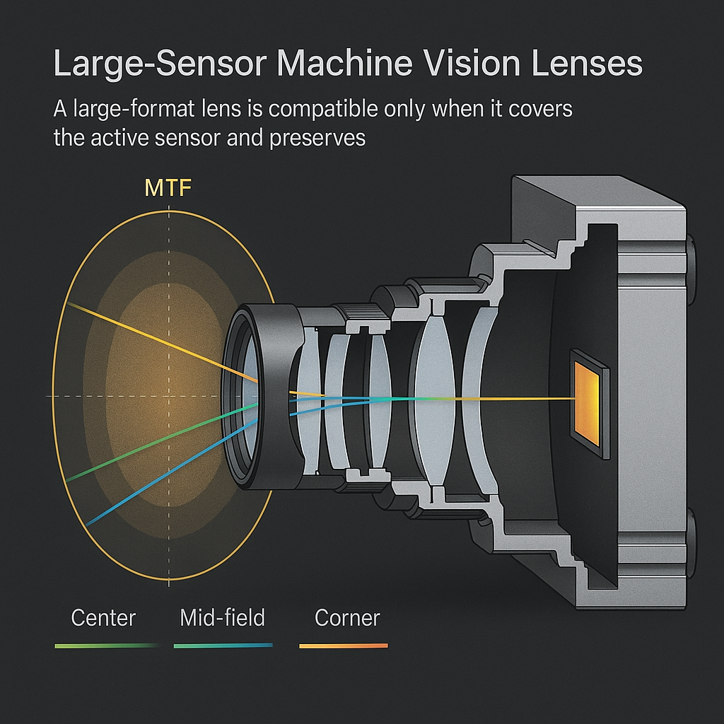
- Review center, mid-field and corner MTF at the required aperture, working distance, wavelength and spatial frequency.
- Treat coverage, brightness uniformity and edge sharpness as separate acceptance criteria because one does not guarantee the others.
- Measure distortion in the deployed geometry and decide whether native optical performance or calibrated correction fits the measurement workflow.
- Test the complete camera stack, including mount, filters, cover glass, sensor microlenses and illumination spectrum, before production approval.
The Short Answer
A large-format lens is compatible only when it covers the active sensor and preserves acceptable sharpness, illumination, geometry and spectral response at the edges. Calculate the sensor diagonal, but do not stop at image-circle diameter. Compare field-based MTF, relative illumination, distortion and chromatic data at the intended aperture, working distance and wavelength. Also verify mount clearance and the sensor stack’s response to oblique rays. Final approval should come from images or measurements made with the production camera, lighting and mechanical configuration.
Selecting Large-Sensor Machine Vision Lenses is a system-matching exercise. A lens can project light onto every active pixel yet still produce corners that are too soft, dark or geometrically displaced for the inspection. Buyers comparing Machine Vision Lenses therefore need conditional data, not a bare sensor-format claim.
Large-Sensor Machine Vision Lens Compatibility Evaluation Table
| Evaluation Item | What to Compare | Why It Matters | Potential Risk if Overlooked | Information to Request |
|---|---|---|---|---|
| Active sensor diagonal | Active width and height; calculated diagonal versus image circle | Establishes geometric coverage | Cutoff or incomplete field | Active-area dimensions |
| Lens image circle | Usable diameter and stated test conditions | Format labels may not define usable edges | Covered but degraded corners | Coverage plot and conditions |
| Corner MTF | Center, mid-field and corner data at the relevant frequency | Tests field-wide resolution | Soft edges or variable detection | MTF plots, aperture, distance and wavelength |
| Relative illumination | Center-to-corner response at the intended aperture | Tests brightness uniformity | Shading and unstable thresholds | Illumination plot |
| Distortion | Full-field error at the intended geometry | Affects position and dimensional measurement | Bias or calibration burden | Distortion plot and test distance |
| Chief-ray angle | Lens ray angles versus sensor-stack requirements | May affect edge response | Shading, color shift or lower pixel response | CRA data and sensor-stack limits |
| Chromatic performance | Focus and registration across operating wavelengths | Tests spectral compatibility | Fringing, blur or focus shift | Spectral range and chromatic data |
Why Large-Sensor Machine Vision Lenses Need More Than a Format Label
The limitations of nominal sensor-format compatibility
A format label is a screening tool, not an acceptance specification. It may indicate nominal coverage without defining edge resolution, illumination, distortion, wavelength, aperture or working distance. Official large-format lens documentation describes product families with image circles from 30 mm to 100 mm and explicitly connects sensor-diagonal matching with avoidance of shading and data loss. Those statements verify the relevance of matching; they do not establish that every lens in a nominal class suits every camera.
Why center-image performance does not predict corner performance
Off-axis image points travel through a different part of the optical system than axial points. The buyer-facing implication is straightforward: a center-only resolution value cannot certify the full sensor. Request field plots or samples extending to the actual corner image height.
The system risks of vignetting, blur, color shift, and geometric error
These failures have different consequences. Shading can move a fixed detection threshold. Blur can reduce defect contrast. Distortion changes where a feature appears, while lateral color can separate wavelength channels near the field edge. Engineering inference: combining them into a single pass/fail statement hides which correction—optical, mechanical or computational—is required.
Start With Sensor Diagonal Compatibility and Image Circle
How to calculate the active sensor diagonal
For active width W and height H, the diagonal is √(W² + H²). A 36 mm × 24 mm active area therefore has a diagonal of approximately 43.3 mm. This is a geometric calculation, not a recommendation for a 43.3 mm image circle.
Use active imaging dimensions rather than package size or a legacy format name. For line-scan designs, evaluate the illuminated sensor length and any required alignment allowance; the related guide to line scan sensor lens coverage explains why pixel count and pitch must be considered together.
How to compare sensor diagonal with machine vision lens image circle
The image circle is the diameter of the image formed at the sensor plane. The sensor diagonal is the longest corner-to-corner dimension of the active area. For Large-Sensor Machine Vision Lenses, the useful comparison is not simply diagonal ≤ image circle; it is whether the manufacturer defines that circle as illuminated, mechanically unobstructed or performance-qualified.
Review machine vision lens image circle specifications alongside MTF and distortion conditions. If the coverage diameter has no aperture, conjugate or wavelength attached, ask how it was established.
Why image-circle margin matters for alignment and usable field coverage
There is no universal margin that guarantees compatibility. Engineering inference: extra diameter may accommodate sensor decenter, lens-to-sensor tilt or a slightly larger active area, but nominal surplus does not repair weak optical performance at that larger image height. Set margin from tolerance analysis and then test the resulting worst-case corner.
Image circle versus field of view: what each specification tells buyers
Image circle describes coverage at the image plane. Field of view describes object-space extent for a defined sensor, focal length, focus distance and system geometry. A lens can cover the sensor yet frame the wrong object area; it can also deliver the required field while failing edge-quality criteria.
Evaluate Edge Quality Across the Full Sensor Area
Reading corner MTF performance at the required spatial frequency
MTF indicates how contrast is transferred at a stated spatial frequency. Compare center, intermediate field points and the corner at the frequency relevant to the inspection—not merely at the frequency that produces the most attractive curve. The manufacturer’s industrial lens selector and chart resources are one verified example of side-by-side MTF and distortion data availability.
Sagittal and tangential performance differences near the image edge
Sagittal and tangential curves represent differently oriented detail. Engineering inference: widening separation near the edge warns that feature orientation may influence measured contrast or apparent sharpness. Ask whether the plotted image height reaches the corner of the selected sensor rather than stopping at a smaller nominal format.
How aperture, focus distance, and wavelength affect edge results
Aperture changes the balance between aberration control, diffraction and available light. Focus distance changes the optical conjugates, and wavelength changes focus and aberration behavior. Consequently, corner MTF performance published under unrelated conditions is insufficient evidence for the deployed system.
How to evaluate edge quality in machine vision lenses using vendor data and sample images
For Large-Sensor Machine Vision Lenses, request plots with test conditions and obtain production-representative images when the acceptance limit is tight. Use a target that reaches every corner, lock exposure and focus, and inspect center-to-edge contrast consistently. This is a recommended validation method, not a claim that one target design suits every inspection.
Check Relative Illumination and Vignetting Before Selecting a Lens
What relative illumination and vignetting reveal about corner brightness
Relative illumination reports edge brightness relative to a reference point, commonly the center. The acceptance limit should come from the application: segmentation, photometry and cosmetic inspection can tolerate different nonuniformity. Compare data at the intended aperture because the result is conditional.
Separating optical vignetting from mechanical shading
Optical falloff originates in the imaging geometry and lens design; mechanical shading can come from a mount, adapter, filter holder, aperture structure or enclosure. A practical diagnostic is to inspect whether changing the mechanical configuration or aperture changes the shape and location of the dark region. That diagnostic is an engineering recommendation, not a guaranteed root-cause test.
How sensor microlenses, filters, and mounts can affect edge illumination
The lens does not operate alone. Oblique rays at large image heights encounter the sensor’s microlenses, cover glass, color filters and any added optical filter. Engineering inference: a lens-only illumination plot may not reproduce camera-level edge response when the sensor stack differs from the test setup.
When flat-field correction can and cannot solve illumination falloff
Flat-field correction can normalize repeatable brightness variation when adequate signal remains. It cannot recover clipped pixels, restore contrast lost to blur, remove a hard mechanical cutoff or eliminate extra noise created by amplifying a weak corner signal. Capture correction frames under the same optical and illumination configuration used in production.
Confirm Distortion for Measurement and Inspection Applications
How machine vision lens distortion changes dimensional accuracy
Distortion displaces image points from an ideal mapping. In gauging or coordinate extraction, that displacement can become systematic measurement error. Request a full-field plot and clarify whether the stated value is maximum distortion, a fitted residual or another metric.
Barrel, pincushion, and mustache distortion patterns
Barrel distortion bends magnification one way across the field; pincushion bends it the opposite way. More complex non-monotonic patterns are often called mustache distortion. The label is less useful than a calibrated map showing error across the actual region of interest.
When software calibration is appropriate and when low native distortion is required
Calibration is a reasonable option when geometry is stable, residual error is validated and resampling is acceptable. Low native distortion is preferable when calibration cannot be maintained, latency is restricted, edge pixels cannot be discarded or traceable measurements require a simpler error budget. This is a workflow decision rather than a universal optical rule.
Distortion checks at the intended working distance and field of view
Do not transfer a distortion result from an unrelated setup without review. Measure the production working distance, focus setting and field of view, then retain residual-error results after correction. Also check whether lens or camera replacement requires recalibration.
Match Chief-Ray Angle to the Image Sensor Stack
What chief-ray angle for image sensors means in a large-format camera
Chief-ray angle describes the direction of the principal ray reaching a given image point relative to the sensor normal. The angle generally deserves more attention toward large image heights, where rays can reach the sensor more obliquely.
Potential effects on corner shading, color response, and pixel efficiency
Engineering inference: if lens ray angles and the sensor’s angular acceptance are poorly matched, edge pixels may respond differently from center pixels. Possible symptoms include shading, channel-dependent response or reduced signal. These outcomes depend on sensor architecture, so CRA should be treated as a compatibility input rather than a stand-alone lens grade.
Why cover glass, filters, and sensor architecture must be considered together
Request the camera maker’s stack thickness, filter arrangement and any CRA guidance, then compare those inputs with lens data. Added filters can also alter the optical path. Approval should use the final camera configuration, especially when filters or protective windows differ from the lens supplier’s evaluation setup.
Verify Chromatic Performance for Your Illumination and Inspection Task
Axial and lateral chromatic effects across a large sensor
Axial chromatic error changes best focus with wavelength. Lateral chromatic error changes image scale or feature position across wavelengths and often becomes more visible away from the center. Engineering implication: a lens that focuses one narrow band well is not automatically qualified for broadband or multichannel registration.
How monochrome, color, multispectral, and broadband systems differ
A monochrome sensor still needs spectral matching when illumination spans multiple wavelengths. Color and multispectral systems add channel-registration requirements. For infrared projects, the separate guide to SWIR lens spectral matching covers sensor sensitivity, lighting and coatings as a combined decision.
Focus shift and edge color errors across the operating wavelength range
Specify actual illumination bands and filter passbands rather than broad labels such as visible. Test focus and edge registration at each operating band. If refocusing between bands is allowed, document the mechanism and repeatability; if not, define a shared-focus tolerance before selecting the lens.
Large-Format Camera Lens Selection Checklist
Inputs to provide when requesting lens recommendations
Provide the camera model, active width and height, pixel size, working distance, required field of view, object depth, illumination wavelengths, aperture target, mount, filter stack, environmental constraints and allowable edge limits. Include whether images support detection, identification, gauging or photometric analysis.
Questions to ask when comparing large-format camera lenses
Ask what usable image circle means, where the MTF curves end, and which aperture, distance and wavelength produced each plot. Request relative-illumination and distortion data under comparable conditions. Clarify mount clearance, sensor-stack assumptions, focus retention and sample-to-sample acceptance criteria.
Acceptance-test criteria for coverage, illumination, sharpness, and distortion
Write separate limits for corner cutoff, relative illumination, center-to-corner sharpness, distortion residual and chromatic registration. Test nominal and tolerance-limit configurations rather than one ideal assembly. Record software correction, exposure and focus settings so a later replacement can be judged against the same baseline.
For a compatibility review, submit those inputs and the acceptable edge-performance limits. Applications that cannot be met by an available catalog lens may require custom optical lens assemblies matched to the sensor, mount, wavelength and mechanical envelope.
Frequently Asked Questions
How much image-circle margin should a machine vision lens have beyond the active sensor diagonal?
There is no universal percentage or diameter allowance. Set the margin from sensor-position, lens-mount, tilt and manufacturing tolerances, then verify performance at the worst-case image height. A larger nominal circle helps only if illumination, MTF and mechanical clearance remain acceptable throughout that added area.
Can a lens cover a large sensor but still produce unusable corners?
Yes. Geometric coverage only shows that image-forming light reaches the sensor area. Corners may still fail because of low MTF, illumination falloff, mechanical shading, distortion, chromatic displacement or sensor-stack mismatch. Qualification therefore needs field-based performance data and representative images, not image-circle diameter alone.
Should corner MTF be evaluated at the same spatial frequency as the sensor sampling requirement?
Evaluate MTF at frequencies tied to the inspection task and sensor sampling, while also reviewing the curve across a useful frequency range. One point does not describe all feature sizes. Keep aperture, working distance, wavelength, focus and image height consistent with production conditions when making the comparison.
Can software correction compensate for vignetting and distortion in a measurement system?
Software can correct repeatable shading and calibrated geometric displacement within validated limits. It cannot restore clipped corners, recover detail lost to optical blur or avoid the noise penalty of strongly amplifying dark pixels. Measurement systems also need a controlled recalibration process when camera, lens, focus or geometry changes.
What camera and lens information should be supplied for a large-format compatibility review?
Supply the camera model, active sensor dimensions, pixel size, mount, sensor-stack or filter details, working distance, field of view, object depth, aperture, illumination wavelengths and environmental limits. Add numerical acceptance criteria for edge sharpness, brightness uniformity, distortion, chromatic registration and any permitted software correction.
Topics
Related Articles
Machine Vision Lens MTF: Match Resolution to Camera Pixel Size
14 min read
How to Select a Machine Vision Lens by FOV, Sensor, and Distance
9 min read
Primary Reasons for the Growing Popularity of Machine Vision Lenses
6 min readAbout SUPERIOR OPTICS
SUPERIOR OPTICS specializes in CCTV lenses, machine vision optics, and custom optical solutions for security, industrial imaging, and specialty applications. We also provide professional lens selection and application support.