


Understanding Focal Length and Field of View
A requirements-first guide to relating lens focal length, active sensor dimensions, angle of view, working distance and physical coverage—without overlooking resolution, distortion or mechanical compatibility.
Key Takeaways
A defensible lens shortlist starts with required scene coverage, active sensor dimensions and working distance—not focal length alone.
- Use active sensor width and height rather than a nominal sensor-format label when calculating coverage.
- Compare horizontal, vertical and diagonal angle of view separately because each uses a different sensor dimension.
- Treat calculated focal length as a starting estimate, especially at short working distances.
- Verify image circle, sampling, distortion, aperture and corner performance before approving a lens.
- Give suppliers the working-distance range, coverage, sensor, mount and acceptance conditions in the RFQ.
The Short Answer
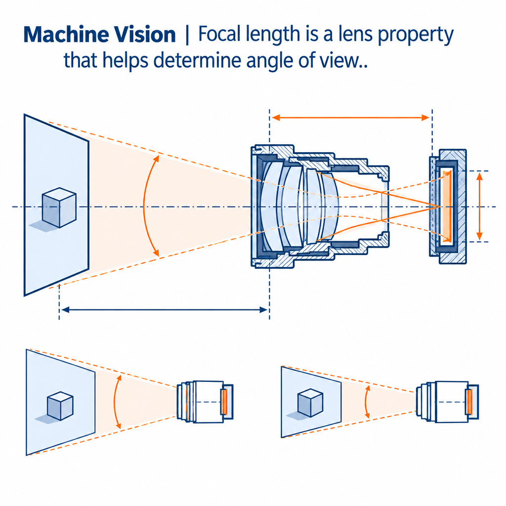
Focal length is a lens property that helps determine angle of view. With the same active sensor, a shorter focal length captures a wider view and a longer one captures a narrower view. Sensor dimensions also matter: the same lens can show different coverage on two cameras. Working distance then determines how much physical area falls within that angle. For procurement, use the calculation only to create a shortlist; image-circle coverage, resolution, distortion, focusing range, aperture, spectral response and mechanical fit still require datasheet review and sample validation.
Focal Length Explained: What It Means in a Camera Lens
What camera lens focal length measures
For a simple lens focused at infinity, focal length is measured between the lens’s optical center and focal plane. A compound camera lens is more complex, so its housing length is not its focal length. Canon’s technical explanation documents this distinction and identifies focal length as a factor governing angle of view.
Why focal length does not define field of view by itself
A millimeter value without the camera sensor is incomplete. The captured view depends on the lens and the dimensions of the sensor’s active area. Working distance is then needed to translate that angular view into coverage at an object plane.
Nominal format labels can be misleading: cameras carrying the same format description may have different active dimensions or aspect ratios, according to Opto Engineering’s optics reference. Obtain active width, height and pixel count from the camera or sensor datasheet.
Focal length vs field of view: the essential distinction
Focal length is a lens specification. Field of view is the scene area imaged onto the sensor. Canon’s field-of-view guide confirms the basic direction of the relationship: shorter lenses show a wider view; longer lenses show a narrower one.
What Is the Relationship Between Focal Length and Field of View?
How does focal length affect field of view on the same sensor?
Hold sensor size constant and shortening the lens widens the angle; increasing it narrows the angle. This does not mean angle changes linearly with the millimeter rating. Wide-angle designs, distortion and focus position can also make catalog coverage differ from a simple estimate.
How sensor active area changes the angle of view
With the same compatible lens, a larger active dimension generally intercepts more of the image and records a wider angle in that direction. This assumes the lens’s image circle covers the larger sensor. If it does not, dark corners or degraded edge quality can make the nominal coverage unusable.
Why the same focal length produces different coverage on different cameras
Two cameras may differ in active width, aspect ratio or crop mode. Compare actual dimensions, not megapixels alone. The practical checks behind M12 sensor coverage and field of view also apply to other compact lens formats.
Angular Field of View vs Physical Field of View
Angle of view: horizontal, vertical, and diagonal measurements
Horizontal, vertical and diagonal values are not interchangeable. Each corresponds to a different sensor dimension. A security specification concerned with corridor width needs horizontal coverage; an inspection checking product height needs vertical coverage.
Physical field of view at the target plane
Physical FOV is the width or height visible where the object sits. It is normally stated in millimeters or meters. Angular FOV is stated in degrees. Mixing the two can produce an RFQ that appears complete but cannot be evaluated.
How working distance changes scene coverage without changing angular field of view
For a fixed lens-and-sensor combination, moving the camera farther from a flat target increases physical coverage; moving it closer reduces coverage. Focus limits may prevent either position from being usable. Working distance should therefore be specified as a range, not merely a preferred value.
How to Calculate Field of View From Focal Length and Sensor Size
Use active sensor width and height instead of nominal sensor format
Collect four values first: active width, active height, sensor diagonal and stated lens focal length. Calculate the diagonal from width and height if the datasheet does not provide it. Do not substitute the lens’s supported optical-format label for an active sensor dimension.
Exact angular field of view formula for rectilinear lenses
A common rectilinear geometric model is:
AFOV = 2 × arctan(sensor dimension ÷ (2 × focal length))
Use consistent units. This model assumes ideal rectilinear projection and a suitable focal-length reference; it does not incorporate distortion, close-focus changes or lens-specific principal-plane positions. Because the supplied verified sources do not independently document this equation, it should be treated here as an engineering model for shortlisting, not a guaranteed product result.
Calculate horizontal, vertical, and diagonal field of view separately
| Direction | Dimension used | Calculation | Procurement use |
|---|---|---|---|
| Horizontal | Active width | 2 × arctan(width / 2f) |
Scene or conveyor width |
| Vertical | Active height | 2 × arctan(height / 2f) |
Object height or corridor depth |
| Diagonal | Active diagonal | 2 × arctan(diagonal / 2f) |
Broad lens comparison only |
Image circle compatibility before finalizing a lens
The calculated angle is irrelevant if the lens cannot illuminate the active area with acceptable corner quality. Check image-circle diameter, compatible sensor size, shading, relative illumination and field-point performance. Lens and sensor matching requires more than comparing nominal formats.
How to Estimate Focal Length From Required Coverage and Working Distance
Start with the required horizontal and vertical inspection area
Record the required scene width and height, including a justified tolerance band. Calculate from both axes. The tighter result governs unless the camera orientation or aspect ratio changes.
Use the physical-FOV approximation to estimate focal length
For an initial long-distance, low-magnification estimate:
estimated f ≈ sensor dimension × working distance ÷ physical FOV
This is a similar-triangle approximation, not a released specification. Working distance definitions vary, and the calculation omits principal-plane location and distortion.
When close-focus applications require lens magnification data or optical simulation
At short distance or meaningful magnification, request the manufacturer’s field, magnification and working-distance data. Thin-lens or paraxial models can help explain behavior, but an actual compound lens may not match a simplified estimate. The broader machine vision lens selection workflow shows where magnification and sampling enter the decision.
Add margin for mounting tolerance, alignment, and usable coverage
There is no universal margin. Derive it from camera-position tolerance, target movement, alignment error, distortion correction and whether edge pixels meet the acceptance threshold. An unexplained percentage can hide risk rather than control it.
Worked Example: Selecting a Focal Length for a Machine Vision Inspection Area
Define the hypothetical inspection area, working-distance range, and sensor dimensions
Illustrative assumptions: a 6.4 mm-wide sensor, 1,600 horizontal pixels, 200 mm required scene width and 500 mm nominal working distance. These values are hypothetical and do not represent a tested SUPERIOR product.
Estimate a focal-length starting point from required coverage
Using the approximation, f ≈ 6.4 × 500 / 200 = 16 mm. A 16 mm candidate is therefore a shortlist starting point. The actual field must be checked at the required focus distance using the selected lens’s data or a physical sample.
Check object-space sampling and pixels per millimeter
Nominal sampling is 1,600 pixels / 200 mm = 8 pixels/mm, or 0.125 mm per pixel. That is sampling, not proven inspection resolution. Lens contrast, focus, lighting, motion and the detection algorithm determine whether a feature can be accepted reliably.
Validate image quality, distortion, depth of field, and mechanical fit
Test center and edge performance at the intended aperture and distance limits. Also review distortion, target depth, exposure time, mount, flange compatibility and barrel clearance. Stopping down may increase depth of field, but it also reduces light and can introduce diffraction-related loss.
Choose the Right Lens Type When Basic Focal-Length Calculations Are Not Enough
| Lens type | Best fit | Main trade-off | Validation priority |
|---|---|---|---|
| Fixed focal | Stable geometry | Coverage changes require repositioning or another lens | Focus and field tolerance |
| Varifocal | Adjustable installation | More setup variables | Locking and repeatability |
| Fisheye | Very wide surveillance view | Non-rectilinear projection | Usable corrected coverage |
| Telecentric | Dimensional inspection | Restricted field and larger optics | Magnification and telecentricity |
| Line-scan-compatible | Moving web or continuous material | One-dimensional sensor geometry | Sensor length and scan synchronization |
Fixed focal length lenses for stable camera positions and repeatable coverage
Where geometry is controlled, fixed focal length lenses reduce adjustment variables. Buyers still need focal-length tolerance, focus-lock method and operating-distance limits.
Varifocal lenses for installation flexibility and coverage adjustment
A varifocal design can absorb uncertain mounting geometry, but adjustment must be controlled. Record the accepted focal setting, focus setting and iris condition so production or field replacements reproduce the view.
Fisheye lenses for ultra-wide surveillance coverage and calibration-dependent use
Fisheye coverage cannot be evaluated with a rectilinear formula alone. Projection mapping and software correction determine how many useful pixels remain in a region of interest.
Telecentric lenses for dimensional inspection where perspective error matters
Telecentric optics can reduce apparent size change caused by object-distance variation within their designed range. Selection is driven by object field, magnification, sensor coverage and working distance rather than focal length alone.
Line-scan lens considerations for long or moving web inspection
Line-scan systems require sensor length, pixel pitch, magnification and motion synchronization. The line-scan sensor and lens coverage guide explains why pixel count alone does not establish lens suitability.
Validate Resolution, Distortion, and Image Quality Across the Required Field of View
Calculate object-space sampling from field of view and pixel count
Divide scene width by horizontal pixels, and scene height by vertical pixels. Use the axis tied to the smallest feature. A wider view spreads the same pixel count across more object space, reducing nominal pixels per millimeter.
Assess lens resolution, sensor pixel pitch, contrast, and lens MTF together
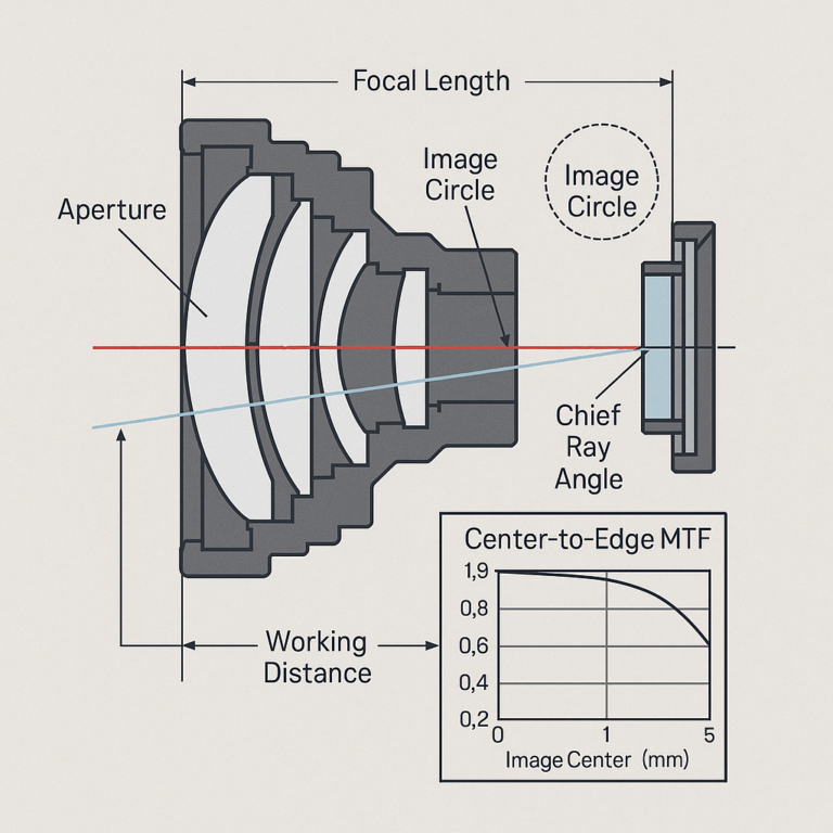
Sampling does not guarantee resolved contrast. Review lens MTF at relevant spatial frequencies and field positions, sensor pitch, processing and required feature contrast as a system. A center-only figure is insufficient when inspection occurs near a corner.
Account for distortion, field curvature, vignetting, and corner performance
Distortion changes position and scale across the image. Field curvature can leave edges defocused when the center is sharp, while vignetting reduces corner brightness. Establish whether correction is allowed and whether acceptance applies before or after calibration.
Balance aperture, depth of field, diffraction, illumination, and motion blur
A smaller aperture can extend depth of field but requires more light or exposure and may reduce fine-detail contrast through diffraction. Moving targets limit exposure time. Choose aperture only after lighting, motion and required contrast are known.
Account for Installation and Environmental Constraints Before Lens Release
Confirm mount, back focal length, barrel clearance, and enclosure-window effects
The camera and lens mounts must share the correct flange geometry. Check rear-element clearance, focus travel, connector access and enclosure interference. A protective window can add reflection, focus shift or aberration, particularly if tilted or used with a wide-angle lens.
Check minimum object distance, focus travel, and working-distance tolerance
A candidate may calculate correctly yet fail to focus at the installation distance. Review minimum object distance and lockable focus range, then validate the full mechanical tolerance stack.
Specify spectral response and infrared focus requirements
Visible and infrared wavelengths may not focus at the same plane. Systems switching illumination bands need documented spectral performance or refocusing provisions. Purpose-designed infrared camera lenses for night surveillance are the relevant starting category, but application testing remains necessary.
Plan calibration, acceptance testing, sample approval, and change control
Define test distance, target, aperture, illumination, focus method, software correction and pass/fail field points. Sample approval should identify the tested configuration. Production change control matters when optical or mechanical substitutions could alter coverage.
OEM Lens Specification Checklist for Focal Length and Field of View
| Requirement category | Information to provide | Buyer-facing consequence |
|---|---|---|
| Coverage | Horizontal and vertical FOV; distance range | Establishes initial lens geometry |
| Sensor | Active width, height, pixels and pitch | Controls angle, sampling and coverage |
| Optics | Image circle, distortion, MTF field points, aperture | Determines usable—not merely nominal—field |
| Mechanics | Mount, flange geometry, envelope and focus lock | Prevents fit and focus failures |
| Environment | Temperature, vibration, window and spectral band | Exposes operating-condition risks |
| Release control | Test setup, approved sample and change notice | Supports repeatable procurement |
An OEM consultation should begin with those values, plus minimum feature size and whether calibration is permitted. Submit them with the RFQ so focal length, image circle, distortion, spectral response and mechanical fit can be reviewed as one system rather than separate catalog fields.
Frequently Asked Questions
Does a larger sensor always provide a wider field of view with the same focal length?
A larger active sensor dimension generally records a wider view with the same compatible lens, but only if the image circle covers it adequately. Crop modes, different aspect ratios, shading and poor corner performance can reduce the usable gain. Compare active dimensions and lens coverage data rather than nominal format names.
Should I calculate field of view using sensor width, height, or diagonal?
Use the dimension aligned with the requirement. Sensor width determines horizontal angle, height determines vertical angle and diagonal determines diagonal angle. Calculate both horizontal and vertical coverage for procurement. A diagonal result alone can conceal insufficient width or height when the sensor and required scene have different aspect ratios.
Why can two lenses with the same stated focal length show slightly different coverage?
Actual coverage can differ because of distortion, focal-length tolerance, focus distance, internal optical design and the reference used for a simplified calculation. Camera crop settings and active sensor dimensions add further variation. Treat the marked value as a selection input, then compare manufacturer field data or validate samples at the intended distance.
Can I use a focal-length estimate for close-up machine vision inspection?
Use it only as a starting estimate. At close focus, magnification, principal-plane location, distortion and lens focusing behavior can make simple distance-based calculations inaccurate. Request lens-specific magnification or field data for the intended sensor and working distance, then validate coverage, focus and edge performance with a sample configuration.
How much extra field of view should be included for installation tolerance?
There is no universal percentage. Build the allowance from camera-position tolerance, target movement, alignment error, distortion correction and the portion of the image that meets resolution requirements. Document each contributor in millimeters at the object plane. Excess margin can unnecessarily reduce pixels per feature, so wider is not automatically safer.
Topics
Related Articles
Lens Specifications Explained: Focal Length, F-Number, and MTF
8 min read
Optical Lens Quality Control: MTF, Distortion, and Centering
11 min read
Applications and Alternatives of a Fixed Focal Length Lens for Security Monitoring
6 min readAbout SUPERIOR OPTICS
SUPERIOR OPTICS specializes in CCTV lenses, machine vision optics, and custom optical solutions for security, industrial imaging, and specialty applications. We also provide professional lens selection and application support.