


Lens Sensor Matching: Image Circle, Pixel Size and Mounts
A camera-first guide to matching image circle, pixel pitch, field performance, chief ray angle and mechanical integration before approving a lens.
Key Takeaways
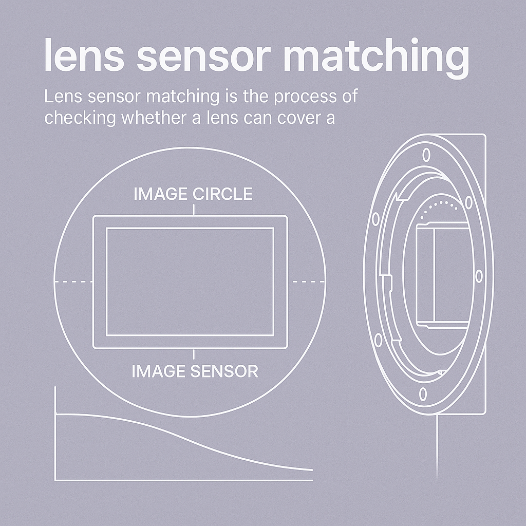
Lens sensor matching requires separate checks for geometric coverage, usable image detail, angular response and mechanical integration. A compatible thread or a matching megapixel label cannot replace these checks.
- Use the sensor’s active width and height in millimeters rather than treating its optical-format label as a measured diagonal.
- Check image-circle coverage separately from corner sharpness and relative illumination.
- Relate pixel pitch to task-level detail and request optical evidence under the intended operating conditions.
- Confirm the mount, focus adjustment, sensor stack and physical clearance together.
- Approve the assembled camera configuration with documented center, edge and corner tests before committing to volume.
The Short Answer
Lens sensor matching is the process of checking whether a lens can cover a camera’s active sensor area and deliver useful image quality in the assembled system. Start with the sensor model, active dimensions, pixel pitch, readout mode and spectral band. Then verify usable image circle, field-dependent MTF, chief ray angle, mount geometry and the cover-glass or filter stack. Test the proposed lens with the actual camera and illumination. Geometric coverage is the first screening step; it does not establish corner performance or suitability for a particular inspection task.
Start With a Camera Record, Not a Lens Label
For a distributor, brand owner or camera OEM, the most useful first document is a short camera specification. It connects purchasing language to information an optical engineer can check. Obtain the sensor manufacturer’s datasheet and the camera or module drawing before asking whether an existing lens will fit.
| Input | What to record | Why it belongs in the inquiry |
|---|---|---|
| Sensor identity | Manufacturer, part number and relevant revision | Similar sensor names can conceal different active areas or stack arrangements |
| Active area | Width and height in mm; active pixel count | Establishes the area the lens must cover |
| Pixel pitch | Micrometers per pixel | Provides the sampling scale for the image-quality discussion |
| Readout mode | Full frame, region of interest and any processing resize | Defines the sensor area and data actually used by the application |
| Spectrum | Illumination band, filter and day/night states | Establishes which optical conditions need validation |
| Integration | Mount drawing, available focus travel and camera stack | Identifies whether the optic can reach and retain the required focus |
| Task | Coverage, working distance and smallest relevant feature | Connects the camera specification to the buyer’s actual purpose |
An optical-format name is useful for initial catalog filtering. For an engineering decision, use the active dimensions. Edmund Optics’ sensor-size explanation shows why changing sensor area affects both coverage and the recorded field of view.
Calculate the Active Sensor Diagonal
For a rectangular sensor with active width W and height H, calculate its diagonal as:
D = sqrt(W² + H²)
Use the same length unit for every term. The following is an illustrative geometry example, not a specification for a SUPERIOR product or a guarantee of image quality.
| Example input or result | Value |
|---|---|
| Active width | 12.8 mm |
| Active height | 9.6 mm |
| Calculated diagonal | 16.0 mm |
| Lens with a stated 12 mm image circle | Fails the full-sensor geometric screen |
| Lens with a stated 16 mm image circle | Nominal geometric match; verify how usable coverage is defined |
| Lens with a stated 18 mm image circle | Passes the nominal size screen; image quality and integration still require evidence |
Ask where the supplier’s coverage claim applies: at which focus distance, aperture and wavelength, and with which definition of acceptable edge quality. Also review centering, tilt and assembly tolerances. Do not turn a nominal diagonal calculation into an unqualified approval.
Separate Coverage, Illumination and Detail
Three tests answer three different questions:
- Coverage: Does the projected image reach the required sensor area without unacceptable clipping?
- Illumination: Is the field response sufficiently even for the intended exposure and image processing?
- Detail: Is there enough contrast at the required feature sizes across the working field?
Edmund Optics discusses the distinction between relative illumination, roll-off and vignetting. A lit corner can still be soft; a sharp corner can still be too dark for a low-signal inspection. Request evidence for the failure mode the application actually needs to control.
For example, a camera reading labels near all four frame corners needs corner checks. An application using only a central region should state that region explicitly. A successful center-only trial does not validate a full-frame claim.
Match Pixel Pitch Without Relying on Megapixel Ratings
Pixel count describes a sampling grid, not a lens test method. Two cameras with the same pixel count can have different physical sensor areas and pixel pitches. Likewise, a lens advertised with a megapixel number may not disclose aperture, wavelength, object distance or field position.
Request MTF data at task-relevant spatial frequencies, with center and off-axis results under the planned operating conditions. Keep a distinction between a design curve, a measured sample and a production acceptance limit. Use the broader lens specifications guide to organize these requests; use the M12 resolution and CRA guide for compact board-camera details.
If the camera uses a smaller region of interest, document both the new coverage and the remaining pixel count. Cropping can exclude poor corners, but it can also remove required scene coverage. It does not change the physical pixel pitch.
Review Chief Ray Angle and the Sensor Stack
Chief ray angle, or CRA, describes the angle of the chief ray arriving at a field position on the sensor side. Obtain the lens profile and the sensor vendor’s angular-response guidance. Where that guidance is unavailable, keep the issue open for module testing rather than inventing a universal permissible angle.
Basler’s C23-1616-2M-S documentation provides a concrete example: it lists image circle and CRA separately and flags possible peripheral illumination reduction for a particular sensor-format use. This illustrates why a coverage label alone cannot establish angular compatibility. It does not set a general limit for other cameras or SUPERIOR lenses.
Include cover glass, IR-cut filters, bandpass filters and protective windows in the configuration record. Ask the optical team whether their thickness, position and optical properties affect the proposed design. A lens evaluated on a bare sensor should not be assumed equivalent to the final camera module.
Check Mechanical Compatibility Before Ordering Samples
Confirm the interface drawing, not only the mount name. Review thread engagement or flange reference, back working space, rear-element clearance, focus travel, locking method and any adapter. Ensure the intended focus can be reached without interference with the sensor cover or filter.
For compact modules, start with the M12 lens portfolio. For industrial cameras, review the machine vision lens range after the sensor and installation constraints are defined. A product-family page is a sourcing route; it does not replace a compatibility review for the chosen camera.
Use a Three-Gate Sample Approval Record
This is a suggested engineering workflow, not a claimed SUPERIOR test result or a universal acceptance standard.
| Gate | Evidence to collect | Decision |
|---|---|---|
| Geometry and fit | Active area, lens drawing, usable image circle and focus reach | Reject incompatible combinations before image testing |
| Image formation | Center, edges and corners at the intended band, aperture and distance | Document detail, shading, color response and focus behavior |
| Production configuration | Final mount, filters, focus lock and representative operating conditions | Approve the configuration and record which revisions require retesting |
Record the camera settings, illumination, target, focus procedure, file processing and pass/fail method. Preserve representative images together with the hardware revision. A later camera substitution should trigger a review of the affected checks rather than silently inheriting the original approval.
Send a Complete Lens Sensor Matching Inquiry
Send SUPERIOR the sensor datasheet, active dimensions, pixel pitch, required field of view, working distance, spectrum and module drawing. Add the smallest feature or image-quality problem that matters to the buyer. Request a camera-and-lens compatibility review before treating a catalog label as an approved production combination.
Frequently Asked Questions
Does the image circle need to match the sensor diagonal exactly?
The usable image circle must cover the required active area under the intended conditions. An exact nominal diagonal match leaves coverage dependent on the supplier’s definition and assembly tolerances. A larger stated circle is a useful screening advantage, but it still does not establish acceptable corner sharpness, illumination or angular response.
Can I use the same lens on two cameras with the same megapixel count?
Possibly, but identical pixel counts do not establish identical sensor dimensions, pixel pitch, mount geometry or filter stacks. Compare the complete camera specifications and required field of view. Then validate image quality on each configuration; a megapixel label alone cannot justify carrying approval from one camera to another.
Does a smaller region of interest solve sensor matching problems?
A smaller region can avoid poorly covered or weak outer areas, but it also changes the active image area and available pixel count. Confirm that the required scene and features still fit. Region cropping does not repair lens performance, change physical pixel pitch or establish mechanical and spectral compatibility.
Is there one safe chief ray angle for all image sensors?
No universal angle should be assumed. Compare the lens’s field-dependent CRA with the particular sensor manufacturer’s angular-response guidance and the module’s optical stack. If those data are unavailable, document the uncertainty and test the assembled camera for corner response, shading and color behavior under the intended illumination.
What should an OEM buyer send before requesting a matching lens?
Provide the sensor model, active dimensions, pixel pitch, readout mode, illumination band, filter stack and mount drawing. Include the required field of view, working distance and smallest important feature. These inputs let the supplier separate coverage, image-quality and integration questions before proposing samples or discussing a custom configuration.
Topics
Related Articles
How to Balance Aperture, Depth of Field, and Diffraction in Vision
10 min read
Lens Specifications Explained: Focal Length, F-Number, and MTF
8 min read
Custom Lens RFQ Checklist: Requirements OEM Buyers Must Define
10 min readAbout SUPERIOR OPTICS
SUPERIOR OPTICS specializes in CCTV lenses, machine vision optics, and custom optical solutions for security, industrial imaging, and specialty applications. We also provide professional lens selection and application support.