Line Scan Sensor Basics: Pixel Count, Pitch, and Lens Coverage
Pixel count alone cannot establish line-camera and lens compatibility. This guide connects pixel pitch, active array length, usable lens coverage, field of view and magnification, with worked calculations and a procurement checklist.
Key Takeaways
A Line Scan Sensor must be evaluated by physical array length and application geometry, not by pixel count alone.
- Calculate active array length from pixel count and pitch before checking lens coverage.
- Treat image-circle diameter as a coverage threshold, not proof of acceptable edge contrast or illumination.
- Recalculate magnification and object-space sampling whenever the camera or inspection width changes.
- Compare lens performance at the proposed wavelength, aperture, magnification and full sensor extent.
- Require camera drawings, mount details and stated optical assumptions in every quotation or substitute review.
The Short Answer
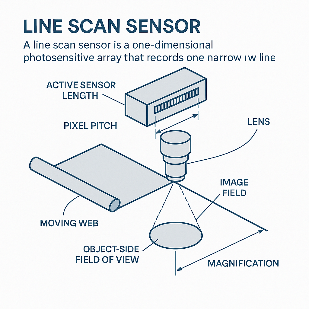
A Line Scan Sensor is a one-dimensional photosensitive array that records one narrow line at a time. Pixel count gives the number of sampling positions, while pixel pitch determines their physical spacing. Multiplying those values provides the nominal active array length. That length must fit within the lens’s usable image field. Field of view is then set by array length and optical magnification—not by image-circle diameter alone. Consequently, cameras with equal pixel counts can require different lenses when their pitch, active length, working geometry, wavelength or optical-resolution requirements differ.
A camera designation such as 8K or 16K answers only one question: how many active sampling positions lie across the line. It does not disclose how wide the array is, what object width it will image or whether an existing lens remains suitable.
That distinction matters when an OEM changes camera vendors, purchasing proposes a substitute, or a machine builder increases inspection width without revisiting the optics.
What Is a Line Scan Sensor?
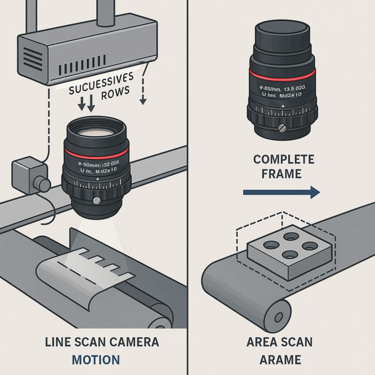
A linear camera uses a one-dimensional pixel array rather than the two-dimensional matrix found in an area camera. The line-camera operating overview identifies pixel count and pixel pitch as core specifications. Relative motion between the object and camera allows successive lines to form a two-dimensional image.
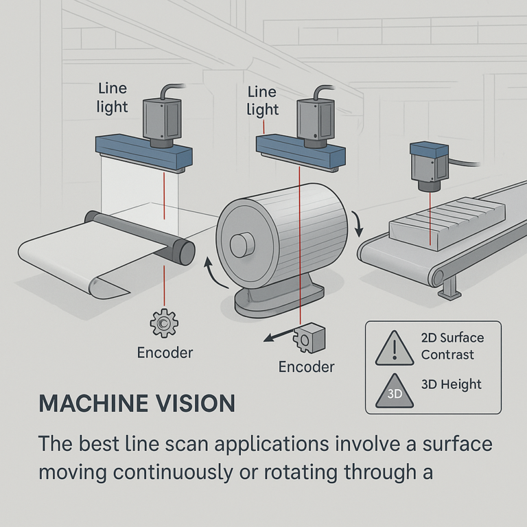
Each exposure therefore captures one narrow cross-section. A web can move beneath a fixed camera; a cylindrical surface can rotate; or a discrete part can travel through the imaging line. The line-scan system guide describes how successive line slices are buffered and assembled into a continuous image.
The terms are not interchangeable:
- Sensor: the photosensitive linear array inside the camera.
- Camera: the sensor plus electronics, timing, interface, housing and mount.
- Lens: the optical assembly that forms the object image on the active array.
Because the active array is predominantly one-dimensional, quotations usually emphasize its length across the scan line. Multi-line color or time-delay-integration architectures can add other dimensions and alignment requirements, so the exact camera drawing still governs.
Reading Pixel Count, Pitch and Active Length
Pixel count is the number of active sampling positions across the line. More pixels can provide finer nominal sampling over a fixed object width, but only if the lens, lighting, motion and signal processing preserve sufficient contrast.
Pixel pitch is the center-to-center spacing between adjacent pixels, normally stated in micrometres. Pitch affects the physical length of the array and the spatial frequency at which lens performance may need evaluation.
Active length is the physical image-space width occupied by the active pixels. For preliminary comparison:
Nominal active length ≈ pixel count × pixel pitch
Convert micrometres to millimetres after multiplying. This is a geometric calculation, not a substitute for the camera manufacturer’s active-area drawing. The drawing should control if the stated pixel count excludes reference pixels, includes inactive positions or uses a more complex sensor architecture.
Worked substitution example
Assume two nominal 16K cameras each have 16,384 active pixels:
- Camera A: 16,384 × 3.5 µm = 57,344 µm, or 57.344 mm.
- Camera B: 16,384 × 5 µm = 81,920 µm, or 81.920 mm.
The arithmetic shows a 24.576 mm difference in nominal active length despite the equal pixel count. This is a derived example, not a claim about any specific commercial camera. Camera B would require substantially greater usable image-space coverage.
Technical Table: Six Specifications That Must Stay Separate
| Specification | Definition and units | Purchasing relevance | Calculation or comparison | What it does not establish |
|---|---|---|---|---|
| Pixel count | Active samples across the line; pixels | Contributes to nominal across-line sampling | Combine with pitch for active length | Array length, field of view or lens quality |
| Pixel pitch | Center-to-center pixel spacing; µm | Changes physical length and lens-resolution considerations | Active length ≈ count × pitch | Object width or full sensor coverage |
| Active length | Physical width of the active array; mm | Sets the minimum nominal image-space span | Compare with documented usable lens field | Working distance, contrast or object resolution |
| Image-circle coverage | Image-space diameter or field supported by the lens; mm | Screens out lenses that cannot cover the array | Usable coverage should extend beyond both active endpoints | Acceptable edge MTF, shading, distortion or field of view |
| Field of view | Object width represented across the line; mm or m | Defines inspection coverage | FOV ≈ active length ÷ magnification | Defect visibility or image-circle adequacy |
| Magnification | Image size divided by object size; ratio or × | Connects sensor dimensions to object dimensions | Magnification ≈ active length ÷ FOV | Mount fit, spectral suitability or optical contrast |
| Object-space sampling | Object width represented by one pixel; µm/pixel or mm/pixel | Helps compare sampling against feature size | FOV ÷ pixel count | Reliable detection, which also depends on system contrast |
These are first-order geometric relationships. Final approval requires supplier data at the proposed operating condition and an application validation image or acceptance test where inspection risk warrants it.
How Lens Coverage Applies to a Linear Array
An image circle is conventionally described as a diameter in image space. A centered one-dimensional array fits across that circle only when its active endpoints remain inside the lens’s supported field. Nominal diameter should therefore be at least the active length; practical selection also needs allowance for tolerances and alignment.
There is no defensible universal allowance. It depends on camera-to-lens concentricity, mechanical stack-up, permitted illumination falloff and the supplier’s definition of usable coverage.
A Line Scan Sensor can be physically inside a stated image circle while still receiving unacceptable performance near its ends. Darkening, reduced contrast, color shift or clipping may appear. Some symptoms can also arise from lighting or alignment, so images alone do not identify the lens as the cause.
Review coverage data for the actual magnification, aperture and wavelength before selecting line scan lenses for industrial inspection. A matching thread or adapter establishes only part of the mechanical interface. It does not prove focus travel, clear aperture, sensor coverage or optical performance.
Sensor Length, Field of View and Magnification
For preliminary sizing, lateral magnification is image size divided by corresponding object size:
Magnification ≈ active length ÷ object-side field of view
Suppose the 57.344 mm array in the worked example must cover a 1,000 mm web:
- Magnification ≈ 57.344 ÷ 1,000 = 0.057344×.
- Nominal object-space sampling ≈ 1,000 ÷ 16,384 = 0.0610 mm/pixel, or about 61 µm/pixel.
These results establish geometry, not defect-detection capability. A 61 µm sampling interval does not guarantee detection of a 61 µm defect. Feature contrast, orientation, lens MTF, exposure, illumination, motion and the detection algorithm remain relevant.
Working distance and focal length constrain whether the required magnification can be achieved within the machine envelope. Principal-plane locations and real-lens behavior make simple thin-lens estimates insufficient for purchasing approval. Use the supplier’s optical data and mechanical drawing; the guide on how to select a machine vision lens by field of view, sensor, and distance covers the broader layout process.
Why Equal Pixel Counts Can Require Different Lenses
Pixel count describes sample quantity. Pitch determines the physical span of those samples. Two 16K cameras can therefore impose very different coverage requirements, as the 57.344 mm and 81.920 mm derived example demonstrates.
Coverage is only the first filter. If both cameras inspect the same 1,000 mm object width, their nominal magnifications would be 0.057344× and 0.081920× respectively. A lens optimized for one operating ratio may not deliver equivalent performance at the other.
Smaller pixels also change the spatial frequencies at which contrast evidence should be examined. That does not mean smaller pixels automatically produce better inspection results. Buyers need lens data under relevant conditions, preferably including center and endpoint performance. The relationship between machine vision lens MTF and camera pixel size explains why sampling and optical contrast must not be treated as the same specification.
Wavelength, aperture, working distance, mount geometry, distortion and illumination interface can create additional differences. Therefore, “supports 16K” is not a complete compatibility statement.
Comparing a Proposed Camera Substitute
Start with the camera datasheets and drawings, then normalize both options in one worksheet:
- Record active pixel count and pitch.
- Calculate nominal length and verify it against the manufacturer’s active-area drawing.
- Compare the new length with documented usable lens coverage—not merely a product-family label.
- Recalculate magnification for the required object width.
- Recalculate object-space sampling and review the minimum feature requirement.
- Check mount, flange geometry, clear apertures, adapters, focus travel and nearby mechanical interference.
- Recheck wavelength range, color architecture, aperture, exposure and full-field optical evidence.
- Identify which assumptions require a sample test before production release.
A proposed Line Scan Sensor substitute with the same pixel count can invalidate the existing lens if pitch increases. A smaller array may avoid clipping but alter magnification and field of view when the lens position remains fixed. Neither direction should be approved from pixel count alone.
Ask the lens vendor to name the camera model and active dimension assumed in the quotation. This prevents an ambiguous statement such as “8K compatible” from being carried into the purchase order without measurable boundaries.
Lens Selection Checklist for Procurement Teams
Camera inputs
- Manufacturer and exact camera model
- Active pixel count, pitch and manufacturer-stated active dimensions
- Sensor architecture: mono, color, multi-line or TDI where applicable
- Mount specification and mechanical drawing
- Relevant wavelength or spectral band
- Interface restrictions around the mount and camera body
Application inputs
- Required object-side field of view
- Smallest feature and acceptance criterion
- Working-distance range and available envelope
- Object motion, line rate and exposure constraints
- Aperture or depth-of-field requirement
- Lighting geometry and illumination interface
- Distortion or measurement limits
Quotation checks
Require the proposed lens model, usable coverage, operating magnification, working distance, aperture, spectral condition, mount, included adapters and supporting full-field performance data. Keep sensor coverage and field of view specifications as separate approval fields; one does not prove the other.
Need a compatibility review? Send the camera datasheet, active dimensions, target field of view, working distance, wavelength, mount and inspection requirement. SUPERIOR can evaluate available optical lens and lens assembly options or identify where a custom configuration may need investigation. Evaluation is not a substitute for application acceptance testing.
Frequently Asked Questions
How do I calculate line scan sensor length from pixel count and pixel pitch?
Multiply the active pixel count by pixel pitch, then convert the result to millimetres. For example, 16,384 pixels multiplied by 3.5 µm equals 57,344 µm, or 57.344 mm. Treat this as a nominal calculation and verify it against the camera manufacturer’s active-area drawing before ordering a lens.
Does a larger image circle always provide a larger field of view in a line scan system?
No. Image-circle diameter describes image-space coverage, while field of view describes object-space width. Field of view also depends on active sensor length and magnification. A larger image circle may accommodate a longer array, but it does not by itself change the system’s field of view or guarantee acceptable edge quality.
Can I use an area-scan lens on a line scan camera?
Possibly, if its usable image field covers the complete active line and it meets the required magnification, wavelength, resolution, distortion and mechanical conditions. The mount must also fit without restricting clear aperture or focus. An area-scan label neither proves nor rules out compatibility; documented operating data should decide.
What information should I send a lens supplier for a quotation?
Send the exact camera model, active pixel count, pitch, active dimensions, mount drawing, field of view, working-distance range, wavelength, aperture or depth-of-field needs, smallest relevant feature, motion conditions and available installation space. Also state any distortion, illumination-interface, environmental and acceptance-test requirements that affect the optical assembly.
What should be rechecked when a line scan camera model is discontinued?
Recheck active length, pitch, field of view, magnification, object-space sampling, usable lens coverage, full-field contrast, wavelength response, mount geometry, clear aperture and focus position. Review exposure and timing if the replacement changes sensitivity or line-rate capability. Do not approve a substitute solely because pixel count and connector type match.
Topics
Related Articles
Line Scan Applications: Web Inspection, Cylinders, and 2D Limits
11 min read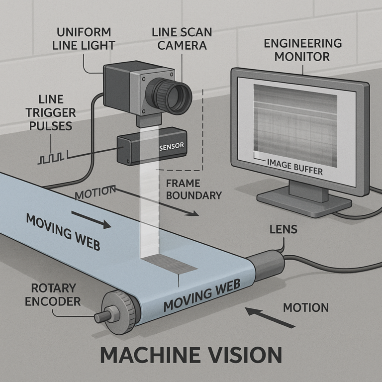
How Line Scan Imaging Works: Motion, Encoders, and Image Capture
11 min read