


M12 Lens MTF Reports: Comparing Nominal, Toleranced, and Measured Data
An evidence-led guide to comparing nominal design curves, tolerance simulations, physical lens measurements and assembled-camera MTF without confusing predicted capability with delivered performance.
Key Takeaways
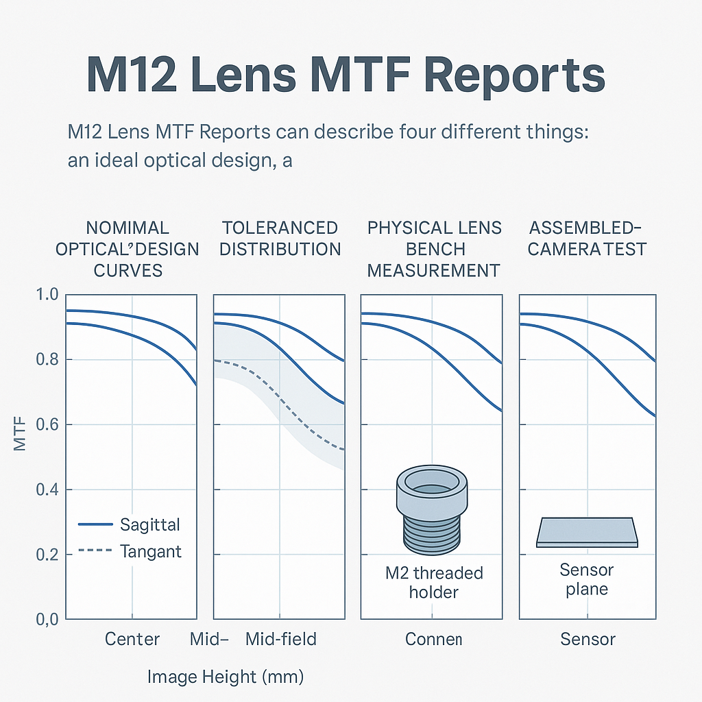
M12 Lens MTF Reports become procurement evidence only when the report type, optical configuration, field points, frequencies, sampling basis and acceptance conditions are explicit.
- Use nominal curves to evaluate design potential, not to approve delivered production lenses.
- Treat tolerance simulations as risk models whose value depends on the errors and distributions included.
- Compare measured results only when aperture, focus distance, spectrum, field position and test method match.
- Require assembled-camera testing when sensor response, alignment, focus or processing can determine application performance.
- Write pass-fail limits, sample quantities, retest rules and change-control requirements into the approved specification.
The Short Answer
M12 Lens MTF Reports can describe four different things: an ideal optical design, a simulated tolerance distribution, measurements from physical lenses or results from complete camera assemblies. They are not interchangeable. A defensible comparison matches aperture, focus distance, spectrum, spatial frequency, field position and measurement method. Nominal and toleranced data support design decisions; measured data support physical verification. If approval depends on the final image rather than the lens alone, test the assembled camera with its intended sensor, filters, focus state and documented processing.
A high curve can still answer the wrong procurement question. The immediate task is to identify what was modeled or tested, under which conditions, and whether the result represents one design, one sample, a sample set or a finished camera.
Why MTF Reports Are Often Miscompared
MTF describes how much modulation, or contrast, an optical system preserves as spatial detail becomes finer. A reported value of 0.4 means 40% of the input modulation was retained at the stated frequency; it does not mean 40% light transmission. Spatial frequency is commonly reported in line pairs per millimeter at the sensor, according to this technical guide to reading MTF curves.
The label “MTF” may sit above a nominal ray-trace result, a Monte Carlo tolerance output, a physical lens-bench measurement or a camera slanted-edge result. Those outputs answer different questions. A favorable nominal curve demonstrates modeled design capability under nominal assumptions. It does not establish how manufactured parts, mounts, sensors or focus operations will behave.
The comparison rule is simple: match evidence type, configuration, test conditions, spatial frequencies and field points before ranking suppliers. If those attributes differ, the curves may still inform engineering review, but they are not an equivalent performance comparison.
The Four Types of MTF Evidence Used in M12 Lens Performance Comparison
| MTF evidence type | Configuration represented | Statistical meaning | What it can demonstrate | Key limitation | Valid procurement use |
|---|---|---|---|---|---|
| Nominal MTF data | Ideal design at stated aperture, distance, spectrum and fields | One theoretical result | Design potential and trade-offs | Excludes actual production and measurement variation | Feasibility and design screening |
| Toleranced MTF predictions | Design with modeled manufacturing or assembly errors | Predicted distribution, percentile or yield | Sensitivity to included tolerances | Depends on model completeness and assumptions | Design review and tolerance negotiation |
| Measured lens MTF | Physical lens in a documented bench setup | Observation from one lens or a stated sample set | Lens performance in that setup | May not represent the camera or production distribution | Prototype, first-article or agreed lot inspection |
| Assembled camera MTF | Lens, sensor, filters, focus and documented processing | Observation from one module or sample set | End-use system response | Does not isolate the lens | Camera-module and application approval |
Nominal and toleranced evidence
Nominal MTF data are calculated from the intended optical prescription. Toleranced MTF predictions add modeled manufacturing and assembly variation. A percentile from that simulation is still conditional on the stated errors, distributions, compensators and analysis settings. It is not a measurement of a delivered lot.
Procurement inference: tolerance output is strongest when used to identify sensitive parameters and plan physical verification. Using a simulated percentile as a receiving-inspection limit confuses predicted risk with observed conformity.
Measured lens and assembled-camera evidence
Measured lens MTF comes from a physical specimen tested under stated conditions. Confidence depends on sample identity, sample count, calibration or traceability information, repeatability and uncertainty reporting. A single “golden sample” can validate that one lens; it cannot by itself describe lot variation.
Assembled camera MTF incorporates the lens, sensor, cover glass, focus, alignment and recorded-image pipeline. A lens bench can isolate component behavior, whereas a slanted-edge camera test measures the combined system. Sharpening can even produce a camera spatial-frequency response above 1, so that output should not be presented as bare-lens MTF.
How to Read Spatial Frequency and Field Position Correctly
One frequency rarely captures an application. Lower frequencies describe the handling of broader structures; higher frequencies represent finer detail. The relevant set should follow the feature being detected or measured and the sensor sampling limit—not whichever frequency gives the most favorable curve.
Pixel pitch provides a sampling reference. For an illustrative 2 µm pixel pitch, sampling frequency is 500 samples/mm and Nyquist frequency is 250 cycles/mm, or 250 lp/mm. Nyquist is a limit derived from sampling, not an automatic lens acceptance target. Contrast at other frequencies may matter more to the task.
Field location matters equally. Image height runs from the optical center toward the edge. Report center, application-relevant mid-field positions and the most demanding used corner or edge. Base those positions on active sensor dimensions, not only on an inch-format label. The wider discussion of M12 lens MTF requirements and sensor matching also covers image-circle and chief-ray-angle considerations.
Sagittal and tangential curves represent perpendicular directional responses at an off-axis image point. Separation indicates orientation-dependent contrast. For inspection tasks with features in multiple orientations, accepting only the better curve can hide a relevant weakness.
What Must Match Before Comparing Supplier Curves
Start with the optical state: focal length or exact part number, aperture, object distance, focus setting and wavelength band. Curves measured at different aperture, spectrum, distance or focus are not directly comparable. Visible-only results cannot establish performance in a filtered near-IR state; buyers evaluating infrared camera lens configurations should identify the operating band and filter state separately.
Then record the camera stack: sensor model, active format, pixel pitch, cover glass, color filter array, microlenses and relevant chief-ray-angle limits. The M12 designation defines an M12 × 0.5 mechanical thread, not focal length, coverage or optical quality. M12 lenses are commonly focused by threading them into or out of a holder and locking them, so holder geometry and focus procedure belong in the test configuration. These interface points are described in an M12 and S-mount technical overview.
Measurement details also need alignment: target type, contrast definition, bench or camera method, illumination, analysis software settings, edge orientation and reporting units. For mechanical and environmental comparisons, retain holder material, mounting torque or locking method, temperature state, vibration exposure and IR-cut-filter position where they affect the intended assembly.
Nominal, Toleranced and Measured Data in an RFQ
Each evidence type supports a different gate:
- Concept selection: request nominal curves at specified wavelengths, aperture, distance, frequencies and fields.
- Design release: request tolerance assumptions, compensators, predicted distribution and sensitivity drivers.
- Pilot approval: test identified physical samples and preserve unit-level results.
- Production acceptance: agree on sampling, method, limits, uncertainty treatment, retest rules and records.
Sample quantity is a commercial and statistical decision tied to production risk; no universal count can be inferred from an MTF curve. The buyer and supplier should agree on how samples are selected and whether acceptance applies per unit, per lot or through periodic process monitoring.
A report should identify serial or lot references where available, test date, equipment or method, calibration status, operator-independent settings, focus rule and raw field-by-frequency results. Summary charts are useful, but they should not erase individual-unit variation needed for approval.
How Assembled Camera MTF Changes the Decision
Good measured lens MTF can coexist with weak camera imagery if the sensor stack is incompatible, focus shifts during locking, the lens is tilted or decentered, or processing changes the recorded response. Conversely, sharpening may make a camera result look stronger without improving optical information in the bare lens.
A practical diagnostic sequence is to preserve the original processing state, check through-focus response, rotate or reseat the lens where the fixture permits, compare field asymmetry and then test a known reference component. Through-focus data can help separate focus error from field curvature, astigmatism or alignment effects, although it does not automatically identify the manufacturing cause.
Buyer decision: use lens-only acceptance when the purchased item is a lens and component isolation matters. Add system-level testing when the contractual output is detection, recognition or measurement from a finished camera module.
A Fair Acceptance Plan for M12 Lens MTF Reports
Write the requirement as a matrix rather than “high MTF.” Rows can represent field positions and sagittal or tangential orientation; columns can represent the agreed spatial frequencies. Each cell receives a minimum, reporting rule or informational designation.
A workable acceptance record also identifies:
- exact lens and sensor configuration;
- aperture, object distance, spectrum and focus procedure;
- field coordinates and frequencies;
- pass-fail limit and measurement uncertainty treatment;
- sample quantity and selection method;
- retest, escalation and disposition rules;
- whether the limit applies to lenses, modules or both.
Approved samples can support visual alignment, but they should not replace measurable limits when repeatable inspection is required. Connect the MTF matrix to broader measured lens MTF and optical lens quality control covering centering, distortion and inspection planning.
Investigating a Supplier-to-Production Gap
First look for a configuration mismatch: object distance, aperture, spectrum, focus criterion, field definition or frequency units. Next check sensor coverage, chief-ray-angle compatibility, filter stack, holder seating, thread lock and camera alignment.
If those match, review the tolerance model against observed failure modes. Was lens-to-holder tilt modeled? Were focus compensation and element decenter distributions realistic? Does the measured sample represent the same revision and lot? Repeat selected units to estimate test repeatability before assigning the discrepancy to product variation.
Engineering inference: a persistent gap may indicate an incomplete model, uncontrolled assembly variable, unsuitable acceptance method or an optical requirement that does not predict the application task. The remedy may be tighter component control, a revised measurement setup or an added system-level validation—not simply a higher nominal curve.
Using MTF Evidence in Lens Approval
An RFQ that asks for M12 Lens MTF Reports should name the evidence required at each project stage. Link the report requirements to the drawing, approved configuration, inspection plan and notification rules for optical, mechanical, coating, holder or process changes.
The broader M12 lens RFQ and approved purchase specification provides a framework for documenting sensor, field of view, working distance and supplier deliverables. For a performance review, provide the sensor format and model, pixel pitch, working distance, wavelength range, field-of-view requirement, critical fields and proposed acceptance conditions. That information determines whether approval needs nominal data, tolerance analysis, physical lens measurements, assembled-camera results or a combination.
Request an M12 lens performance review when the available curves cannot be placed on a common configuration and acceptance basis.
Frequently Asked Questions
What is the difference between nominal and measured MTF data?
Nominal MTF is calculated for an ideal optical design under stated assumptions. Measured MTF is obtained from a physical lens or camera in a documented setup. Compare them only after matching aperture, object distance, focus, wavelength band, spatial frequency, field position and the measurement method used.
Can a toleranced MTF prediction be used as a production acceptance criterion?
Not by itself. A tolerance simulation predicts performance from modeled errors and assumed distributions; it does not observe delivered units. It can guide tolerance negotiation and verification planning. Production acceptance should use an agreed physical measurement method, sampling basis, limits and rules for uncertainty, retest and disposition.
Why can a lens with good measured MTF produce weak camera images?
The camera adds sensor sampling, cover glass, microlenses, color filters, focus, alignment and image processing. A compatibility problem or assembly error can reduce recorded contrast even when the lens passes a bench test. System testing is appropriate when approval depends on finished-camera detection, recognition or measurement.
Which field positions should be included in an M12 lens MTF requirement?
Include the optical center, application-relevant intermediate fields and the most demanding used edges or corners. Express positions as image coordinates or image height tied to the active sensor area. Where orientation matters, include both sagittal and tangential results rather than accepting only the stronger response.
Should MTF acceptance apply to the lens or the assembled camera?
Apply lens-level limits when purchasing and controlling the optical component independently. Apply camera-level limits when the deliverable is a finished imaging module or application result. Many programs need both: lens testing for supplier and process control, followed by system testing for sensor compatibility, assembly focus, alignment and processing.
Topics
Related Articles
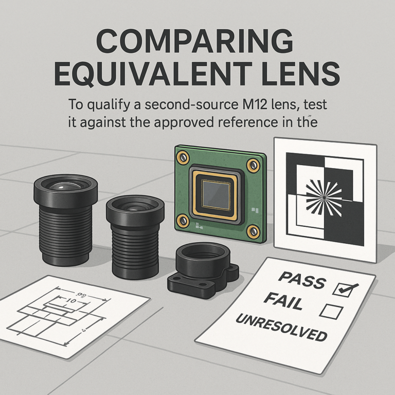
M12 Sample Approval and Second Sources: Comparing Equivalent Lenses
10 min read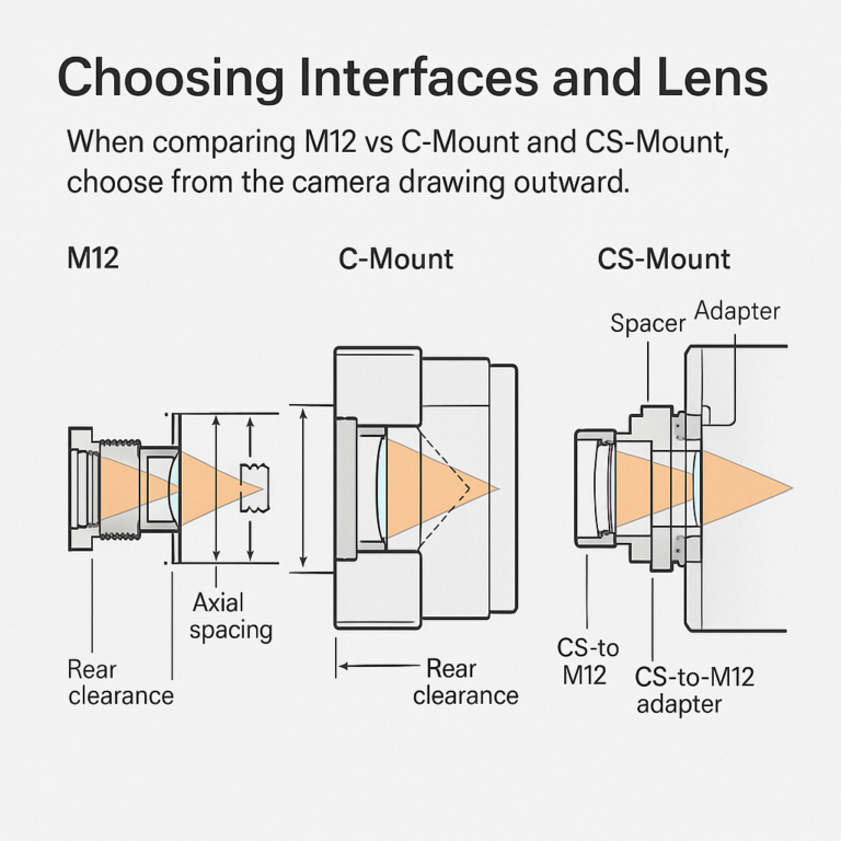
M12 vs C-Mount and CS-Mount: Choosing Interfaces and Lens Adapters
10 min read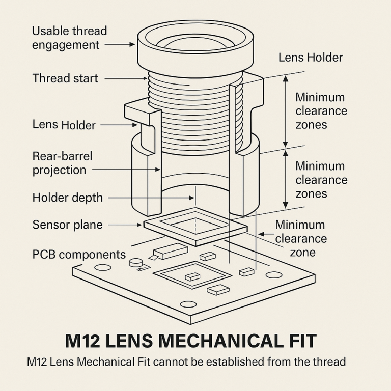
M12 Lens Mechanical Fit: Back Focal Length, Threads, and Clearance
10 min readAbout SUPERIOR OPTICS
SUPERIOR OPTICS specializes in CCTV lenses, machine vision optics, and custom optical solutions for security, industrial imaging, and specialty applications. We also provide professional lens selection and application support.