


M12 Lens Mechanical Fit: Back Focal Length, Threads, and Clearance
A thread match does not prove that an M12 lens will focus, clear the sensor stack or remain interchangeable. This guide separates thread engagement, focus travel and physical-clearance approval.
Key Takeaways
M12 Lens Mechanical Fit should be approved as three separate conditions: secure thread engagement, reachable focus and adequate physical clearance across the full tolerance range.
- Do not approve a lens solely because its thread enters the holder; the focus position and rear mechanical envelope remain independent checks.
- Require controlled lens and holder drawings that identify dimensions from explicit mechanical datums rather than relying on an undefined back-focal-length value.
- Calculate minimum engagement and maximum insertion conditions so the lens neither lacks retention nor bottoms out before focus is reached.
- Check rear and external barrel clearance throughout the available focus travel, including filters, retainers, PCB components, housings and locking features.
- Release production only after drawing review, tolerance analysis and an assembled fit-and-focus test use the same acceptance criteria.
The Short Answer
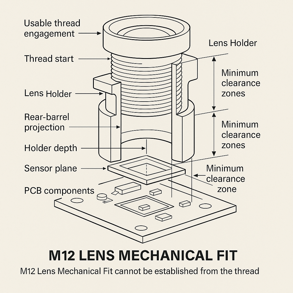
M12 Lens Mechanical Fit cannot be established from the thread designation alone. Approval requires a controlled section drawing of the lens and mating camera assembly, with common datums for the usable thread, shoulder, rear-barrel projection, sensor plane and obstructions. Evaluate thread engagement, focus travel and physical clearance as separate pass-fail conditions. Use tolerance limits rather than nominal dimensions, then test the assembled module at its required working distances. Because no verified universal dimensional values were supplied for this article, obtain model-specific drawings instead of assuming that one holder depth or clearance rule applies to every M12 lens.
Why M12 Thread Fit Does Not Confirm Full Mechanical Compatibility
A lens that starts cleanly in a holder has passed only an initial interface check. It may still reach the end of the holder thread before focus, project too far toward the sensor stack, collide with a housing bore or provide too little engagement at the required focus position.
That distinction affects substitutions. Two catalog entries can share a nominal thread description yet differ in thread start location, usable threaded length, shoulder geometry and rear projection. If purchasing approves the substitute from a summary specification, the mismatch may appear only during camera assembly.
For defensible M12 Lens Mechanical Fit approval, request controlled section drawings for the lens, holder, sensor board and housing. Each drawing should identify its revision, dimensional datums, tolerances and any keep-out zones. A sample that happens to focus is useful evidence, but it does not define production limits.
How do I verify M12 lens thread engagement and clearance?
- Confirm the lens thread designation, pitch, usable threaded length and thread start location.
- Compare them with the holder thread form, threaded depth and any unthreaded lead-in.
- Calculate minimum and maximum engagement across both parts’ tolerance limits.
- Check that the barrel cannot bottom out before reaching the required focus position.
- Compare rear projection with the sensor, cover glass, filter, PCB and retainer envelope.
- Verify focus travel at nominal and limiting assembly conditions.
- Approve the combination through controlled drawings and an assembled fit-and-focus test.
Distinguish Optical Back Focal Length From Mechanical Back Focal Length
What is the mechanical back focal length of an M12 lens?
For procurement purposes, treat mechanical back focal length as a drawing-controlled axial relationship between a stated lens datum and the required image plane. The term is unsafe without those two references. A supplier may use a shoulder, thread reference or another mechanical surface, so the datum definition must accompany the value.
An optical back-focal-length entry and an assembly dimension should not be treated as interchangeable. One describes an optical relationship; the other must let the camera designer locate the lens relative to the sensor using measurable part geometry. Ask the supplier to show both on a section view when both are relevant.
Mechanical approval also does not establish optical suitability. Sensor coverage, image circle and field of view need a separate review; see this guide to M12 lens sensor coverage and field of view.
Buyer consequence: an ambiguous datum becomes an assembly risk
If the lens drawing gives a back-focal-length value but no reference surface, the holder designer cannot build a reliable stack from it. The appropriate RFQ response is clarification, not an assumed datum. Likewise, a nominal focus location is insufficient when tolerance limits can place the required position outside the holder’s adjustment range.
Verify M12 Lens Thread Specifications and Engagement
The thread review needs more than a nominal diameter label. Record the designation exactly as documented, pitch, usable male thread, holder thread depth, lead-in geometry and interruptions such as adhesive channels or locking slots. Do not infer an unspecified thread form or tolerance class.
Engagement and bottoming are different limits
At the required focus position, determine the actual axial overlap between usable lens and holder threads. Evaluate the least-engaged condition for retention and alignment. Separately, evaluate the deepest insertion condition for collision with a thread runout, holder floor, filter retainer or other stop.
A lens can therefore fail in opposite ways: insufficient engagement at one focus limit, or premature bottoming at the other. A go/no-go thread check does not expose either problem unless it reproduces the real holder geometry and focus position.
Locking changes the assembly state. A jam nut consumes external thread and may need radial tool access. Adhesive can migrate into the thread or prevent later adjustment. A set screw can impose side load. These are design-review conditions; their acceptable limits require application-specific validation rather than a universal rule.
M12 Lens Barrel Dimensions and Adjacent-Component Clearance
Request a section drawing that identifies the maximum external envelope, not just a representative outline. Relevant fields include overall length, front and rear barrel diameters, shoulder diameter and location, rear projection, usable thread limits, retaining features and any geometry that rotates or translates during focusing.
The mating cross section should locate the sensor plane, cover glass, IR filter or movable IR-cut mechanism, PCB surface, nearby components, holder floor, housing bore, bezel and lock feature. Compare envelopes through the full planned focus movement, not only at the nominal setting.
Rear clearance is not purely axial. A barrel may clear the sensor cover glass while overlapping a raised board component or filter frame. External interference can also stop installation before the lens reaches focus. CAD interference review is useful, but the release evidence should include tolerance conditions and a physical assembly inspection.
Where only nominal M12 lens barrel dimensions are available, classify compatibility as provisional. A rendering or product photograph cannot establish a maximum material envelope.
Holder Tolerances, Alignment and the Focus-Travel Window
Holder depth and sensor position combine with the lens reference geometry to determine whether focus is reachable. Concentricity and perpendicularity can also affect alignment, although the acceptable optical effect must be established for the camera design rather than inferred from thread fit.
Build the focus window around required operating conditions: target distance, sensor location, filter state and assembly process. For applications still defining focal length, field of view or working distance, the separate machine vision lens selection workflow should precede final holder approval.
The available adjustment range must include the required focus position under the adverse combinations of lens, holder and sensor-stack variation. Reserve space for the selected locking process and for assembly access. If production focus is set with adhesive, record when focus is verified relative to adhesive application and cure; otherwise, process variation can be mistaken for part variation.
A buyer should therefore request both part tolerances and assembly acceptance criteria. Inspecting loose components alone cannot demonstrate that the completed optical stack reaches focus.
Use a Tolerance Stack for Focus and Lens-to-Sensor Clearance
A useful stack starts from one assembly datum and keeps three decisions separate:
- Thread engagement: Is sufficient usable thread overlap available at every approved focus position, without exceeding the insertion limit?
- Focus travel: Does the required focus position remain inside the adjustable range for all allowed part and assembly variations?
- Physical clearance: Does the minimum separation remain positive between the lens envelope and every keep-out envelope throughout adjustment?
Symbolic worked example
Assume the lens drawing defines a focus reference position, usable thread interval and rear-envelope position from datum L. The holder drawing defines the mating thread interval and holder mounting face from datum H. The camera drawing locates the sensor and obstruction envelope from H.
First transform the lens limits into the holder coordinate system at each end of the proposed focus range. Then calculate the overlap of the usable thread intervals, followed by the separation between the transformed rear envelope and the nearest obstruction. Repeat using the adverse tolerance direction for each pass-fail condition. This is an engineering method, not supplier data; actual dimensions must come from controlled drawings.
For M12 Lens Mechanical Fit, do not combine those results into one informal “fits” decision. A design may pass clearance but fail focus travel, or reach focus with inadequate engagement.
M12 Lens Mechanical Compatibility Checklist
| Compatibility check | Lens input | Mating input | Condition evaluated | Failure risk | Approval evidence |
|---|---|---|---|---|---|
| Thread engagement | Pitch, thread start, usable length | Thread form, depth, lead-in | Minimum overlap and maximum insertion | Poor retention, cross-threading or bottoming | Controlled drawings and fit check |
| Focus travel | Focus datum and reference geometry | Sensor position and adjustment range | Nominal and limiting focus positions | Required focus cannot be reached | Stack calculation and assembled focus test |
| Rear clearance | Rear mechanical envelope | Sensor stack and keep-out zones | Minimum separation through travel | Contact, damage or obstruction | Section view and physical inspection |
| External clearance | Maximum diameters and shoulders | Housing, bezel and lock geometry | Radial and axial clearance | Installation or locking interference | CAD review and assembly validation |
| Alignment | Lens reference surfaces | Holder and mounting references | Allowed alignment variation | Image shift, tilt or inconsistent yield | Holder drawing and optical verification |
Create a Mechanical-Fit Approval Package Before Ordering
The RFQ should identify lens and holder drawing revisions, required datums, thread details, rear and external envelopes, sensor position, filter configuration, focus range, locking method and acceptance tests. This M12 lens specification guide can help place those requirements into a sourcing package.
Incoming sample inspection should compare measurable dimensions with the released drawing rather than merely checking whether the sample screws in. Record the assembled focus position, remaining adjustment in both directions, engagement condition and minimum observed clearance. Any measurement method must be suitable for the tolerance being accepted.
Production controls should require review when a lens, holder, sensor board, filter, housing or locking process changes. An alternate lens is not mechanically interchangeable until the same three gates—engagement, focus and clearance—pass against the released assembly.
For drawing review, provide the camera cross section, sensor location, holder drawing, focus range and keep-out constraints before approving samples or volume orders. Buyers can then review suitable fixed focal length lenses or discuss optical lenses and lens assemblies when the mechanical envelope requires a custom approach.
Frequently Asked Questions
Can two M12 lenses with the same thread designation require different holder depths?
Yes. The shared thread designation establishes only one interface condition. Different rear-barrel projections, shoulder locations, usable thread lengths or required focus positions can move each lens to a different axial location. Compare both controlled section drawings and validate the assembled focus range before treating them as substitutes.
What drawing dimensions should an OEM request before substituting an M12 lens?
Request the complete thread callout, usable thread limits, thread start, shoulder position, maximum barrel diameters, overall length, rear projection and focus reference datum. The mating assembly drawing should locate the sensor, filters, retainers, PCB components, housing surfaces and locking feature from compatible datums.
How much focus-travel margin should be confirmed during lens and holder evaluation?
There is no universal margin supported by the supplied evidence. Confirm enough adjustment to contain every required focus position after lens, holder, sensor-stack and assembly tolerances are applied, while preserving engagement and clearance. Document remaining travel in both directions and validate it on the assembled module.
Can an M12 lens interfere with an IR-cut filter or sensor-board components?
Yes. Rear-barrel projection can overlap a fixed filter frame, moving IR-cut mechanism, retainer or raised PCB component even when the lens clears the sensor cover glass. Evaluate axial and radial keep-out envelopes across full focus travel and every filter position, then inspect the assembled camera.
Should mechanical-fit acceptance be performed on individual parts or the assembled camera module?
Use both. Part inspection verifies drawing-defined dimensions and helps control incoming variation, while assembled testing verifies the combined thread engagement, focus range, alignment and clearance. Neither replaces the other: a conforming loose part can still fail when its tolerances interact with the holder and sensor stack.
Topics
Related Articles
M12 Visible and NIR Lens Selection: Wavelengths and Filter Choices
11 min read
M12 Lens Resolution and CRA: Matching Optics to the Camera Sensor
11 min read
M12 Working Distance and Aperture: Specifying Usable Depth of Field
11 min readAbout SUPERIOR OPTICS
SUPERIOR OPTICS specializes in CCTV lenses, machine vision optics, and custom optical solutions for security, industrial imaging, and specialty applications. We also provide professional lens selection and application support.