F-Theta Lenses
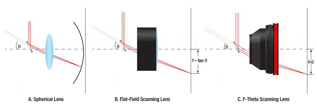
F-theta lens technology has been developed to deliver the best performance possible in laser scanning and engraving systems. These lenses are perfect for image transfer and material processing, as well as engraving and labeling. A planar imaging field will give the best results for many laser scanning and engraving applications. A spherical lens can only image along a circular plane (see Fig. 1 A). The flat-field scanning lens solves this problem. However, the displacement of the beam depends on the product of the effective focal length (f) and the tangent of the deflection angle θ [f × tan (θ), see Fig. 1 B].
This nonlinear displacement is easily accounted for by the software algorithm. However, it would be ideal to have a linear displacement, i.e. a constant scan rate. F-theta lenses are designed with a barrel distortion that yields a displacement that is linear with θ (f*θ, see Fig. 1 C). This simple solution eliminates the need for complex electronic corrections and allows a compact, fast and relatively inexpensive scanning system. 
F-theta lens solutions solve many problems with laser scanning. The compact design of an f-theta allows for a reduction in the number of components required to create a flat plane of image. These lenses can achieve smaller spot sizes which translate to higher resolutions for scanning, printing or engraving, and higher intensities for welding or welding. The most important thing is that the spot size, resolution and intensity are almost constant throughout the image plane.
Scan Lens Setup
Laser scanning systems optimize the laser beam’s waist size (diameter) and its precise position. A laser scanning system may have one or more scan mirrors depending on its function. In a single-mirror system, for example, the mirror is placed at the position of the entrance pupil of the ftheta lens. In a system with two mirrors, the entrance pupil is located between the mirrors. Mirror separation should be kept to a minimum in order to maximize the performance of an f-theta.
Scan Lens Characteristics
When selecting an f-theta, the operating wavelength, scan field diameter (SFD), and spot size are all important considerations. These parameters allow the user to place additional constraints on a scanning system, such as entrance beam size, scanning mirror deflection and mirror placement.
Scan Field Diameter (SFD), or Scan Length is the diagonal of an area square in the image plane that can be focused using the lens. This specification is used to define deflection, along with focal length. The Output Scan Angle (OSA) is the angle formed between the output beam of a laser after it passes through the scanning lens and the plane normal. OSA will change across the entire image field. However, for scanning and engraving, the OSA changes will not have a significant impact on dynamics. Note that the OSA for telecentric lens is always zero. The Back Focal length (BFL), is the distance from the outer glass element (apex) of the lens to the paraxial focus point. The Back Working Distance (BWD) is the distance from the lens housing to the focal point. 
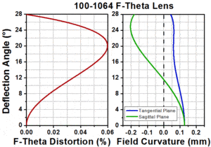
Curvature and field distortion are also important parameters to consider. Although f-theta lens are designed to produce a flat plane of image, the actual lens does not always match up to this. You can expect some distortion and curvature. Figure 2 shows the parameters of our f/theta lens. The focal length is set at 100mm, and the maximum deflection is 28 degrees. Figure 2 shows the field curvature (in millimeters) and f-theta distorsion (in percent) as a function scan angle. In most scanning systems, the zero-curvature is placed at the middle of the scan. This helps to limit the amount curvature that occurs during the scan.
Summary
The laser system’s goal is to create a spot that has the right size for the required resolution, and then accurately place it anywhere on a flat plane. Diffraction-limited scanning lenses, in general, will produce a spot size given by
![]()
where Spot Size is the 1/e2 beam diameter, λ is the wavelength of the laser, f is the effective focal length of the lens, and A is the entrance beam diameter. C is a constant that relates to the degree of pupil illumination and input truncation (for a Gaussian beam, C = 1.83 when the entrance beam is truncated at the 1/e2 diameter). The focal length also influences the diameter of the scan field, which is given by
![]()
where L is the diagonal of the square scan field, θ is the maximum deflection angle in radians, and again f is the effective focal length of the lens. By maximizing θ, the focal length can be minimized in a system. In general this is the preferred method of maintaining L since it will reduce the necessary size of the optics resulting in a more compact and cost effective system. Additionally, f-theta distortions caused by motor instabilities of the scanning mirrors will be reduced since these distortions scale with the EFL (smaller EFL results in smaller distortions).
Related Posts
Photoelectric Sensor Applications
How useful was this post? Click on a star to rate it! Submit Rating As you found this post useful......
Robotic Workers – E-Commerce in the 21st Century
How useful was this post? Click on a star to rate it! Submit Rating As you found this post useful......


