


How to Control Lens Alignment, Tilt, Decenter, and MTF Degradation
A practical engineering guide to separating lens, sensor, housing, assembly and test-system causes when measured MTF falls after optical integration.
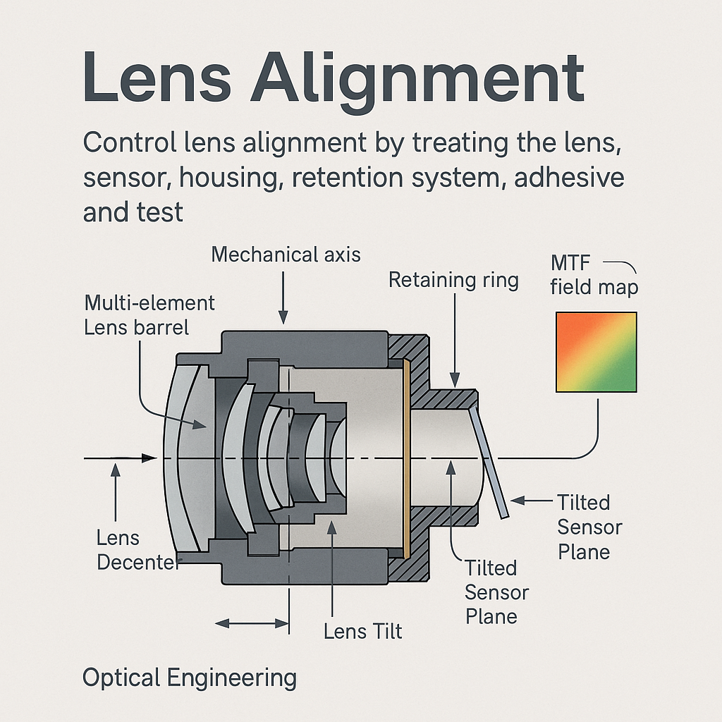
Key Takeaways
Lens Alignment should be accepted against application-level MTF at defined field points, not inferred from mechanical dimensions or standalone lens inspection alone.
- Repeat the measurement with a known-good reference before changing the lens, sensor or housing.
- Use the MTF pattern to separate uniform focus or spacing errors from asymmetric tilt, decenter and seating errors.
- Allocate tolerances from optical sensitivity analysis rather than tightening every mechanical dimension equally.
- Record alignment position, MTF, torque, adhesive and cure data before and after datum transfer.
- Escalate recurring post-assembly failures into datum, retention or assembly-sequence redesign.
The Short Answer
Control Lens Alignment by treating the lens, sensor, housing, retention system, adhesive and test station as one tolerance chain. First establish repeatable MTF measurements at defined field points and spatial frequencies. Then separate uniform losses from asymmetric patterns, checking focus and spacing before tilt or decenter. Monitor performance before retention, after torque, after adhesive cure and after environmental exposure. If passive datums cannot hold the required MTF distribution, use active alignment with controlled datum transfer and post-cure verification.
Why Lens Alignment Can Reduce Measured MTF After Assembly
Design MTF describes the modeled optical configuration. The assembled-system result also includes element placement, sensor position, barrel geometry, retention loads, bonding effects, added windows and measurement variation. MTF itself describes contrast transfer by spatial frequency; it is therefore possible for center performance to remain acceptable while a production-relevant edge frequency fails.
A verified technical discussion from Exosens on optical-system alignment reports that assembled results can fall 10%–20% below design even when specified dimensions, spacers, torque and visual checks appear acceptable. That figure should not be treated as a universal loss allowance. It shows why mechanical conformance alone cannot prove optical conformance.
Tolerance stack-up matters because errors interact. Barrel-bore coaxiality, element centering, seat perpendicularity, spacer thickness and sensor mounting may each be within drawing limits while their combined direction produces unacceptable asymmetry. Conversely, tightening every dimension can raise cost without controlling the most sensitive degree of freedom.
Test variation must be excluded first. Repeat the setup, rotate or remount the unit where practical, verify target or collimator alignment, and run a known-good reference. Guidance on optical lens quality control and MTF testing provides a broader basis for defining repeatability and acceptance criteria.
Root-Cause Checklist for MTF Degradation
A lens can test below design MTF when the assembled optical axis, focal plane or test condition differs from the design condition. Check these causes before rejecting the lens:
- Sensor plane: Inspect tip, tilt, axial position and package or board flatness.
- Lens position: Check lens tilt and lens decenter against functional datums, not only housing edges.
- Focus and spacing: Verify back focal distance, thread engagement, spacers and focus-lock position.
- Retention: Compare MTF before and after retaining-ring installation; inspect seating and torque uniformity.
- Bonding: Record dispense location, adhesive volume, cure profile and pre- versus post-cure movement.
- Added optics: Verify tube lenses, windows, filters and spacers for wedge, tilt and spacing changes.
- Test setup: Confirm target geometry, collimation, illumination, fixture seating and repeated-measurement spread.
Lens Alignment and MTF Degradation Troubleshooting Table
| Observed MTF or image symptom | Likely contributing condition | What to verify | Recommended control or corrective action |
|---|---|---|---|
| One corner or side is lower than its opposite | Sensor tilt, lens tilt, decenter or fixture skew | Best-focus position by field; result after module rotation | Correct functional datums; add tip/tilt measurement or active adjustment |
| All field points are uniformly low | Focus or axial-spacing error; test condition mismatch | Focus sweep, spacer stack and known-good reference | Control axial stack and lock focus only after optical verification |
| Center passes but edges vary inconsistently | Tilt, decenter, seating error or field-dependent test error | Corner map, seat cleanliness and repeat setup | Improve seating control and use multi-field acceptance |
| MTF changes after retaining-ring installation | Uneven force, deformation or element movement | Before/after MTF and torque sequence | Set a validated torque window; redesign the seat or retention method if needed |
| MTF shifts after adhesive cure | Cure shrinkage or loss of alignment during fixture release | Pre-cure, post-cure and post-release coordinates | Control dispense and cure; compensate only after demonstrating repeatability |
| Stations or repeated setups disagree | Fixture, collimation, target or analysis variation | Gauge study and reference-unit history | Correlate stations and lock the measurement recipe |
| Lens passes alone but fails after integration | Sensor, tube lens, window, housing or combined stack | Performance at each assembly stage | Add staged optical gates to identify when the loss appears |
The table is a triage tool, not proof of causation. Several conditions can produce similar MTF maps, so confirmation requires a controlled change or measurement that isolates one variable.
How Does Sensor Tilt Affect MTF?
Sensor tilt makes the sensor plane noncoincident with the image plane. One side can move closer to best focus while the opposite side moves farther away, creating an edge-to-edge or corner-to-corner focus gradient. The diagnostic step is to measure a focus sweep at multiple field points rather than compare only one image at one axial setting.
A diagonal pair that reaches peak MTF at different focus positions is consistent with relative tilt. That is an engineering inference, not a unique diagnosis: lens tilt, a skewed fixture or a tilted target can create a similar pattern. If the module can be rotated in the test fixture, observe whether the low region follows the module or remains fixed to the station.
Field curvature behaves differently. A rotationally symmetric lens may place center and edge best focus at different axial locations while opposite corners remain broadly similar. Persistent directional asymmetry points toward tilt, decenter, seating or test alignment rather than field curvature alone.
How Lens Decenter and Lens Tilt Affect Image Performance
Lens decenter is lateral displacement between an optical axis and the intended reference axis. Lens tilt is angular misalignment. The distinction matters because the corrective mechanism differs: changing radial clearance may reduce lateral movement but will not correct a nonperpendicular seat.
The optical-axis and mechanical-axis guidance identifies barrel and bore geometry, lens-to-bore fit, retaining forces and reference-surface errors as alignment contributors. It also notes that a component can meet individual surface, coating and dimensional requirements while the final system misses expected performance.
Decenter commonly presents as directional asymmetry, including unequal performance at nominally equivalent field points. Tilt commonly produces a best-focus gradient. Neither symptom is exclusive. Coma-like asymmetry may be consistent with decenter, while astigmatic behavior may be consistent with tilt or wedge, but wavefront or Zernike analysis is more discriminating than an MTF pass/fail value alone.
Set Optical Alignment Tolerance Around Functional Performance
Begin with functional datums: the sensor image plane, lens mounting interface, locating diameter, shoulder or another surface that actually transfers position. A cosmetic housing edge is not an optical datum unless its relationship to the optical chain is controlled and verified.
Allocate optical alignment tolerance across the lens, sensor, housing and production fixture using sensitivity analysis. Perturb X, Y, Z, tip and tilt independently in the model or controlled build, then rank their effect on the required field points. This is more defensible than dividing a total tolerance equally among parts.
Acceptance criteria should state wavelength or illumination band, object distance, focus method, field coordinates, sagittal/tangential treatment where relevant, spatial frequencies and analysis settings. A security imager optimized for recognition at a chosen field angle may need a different MTF balance from a machine-vision system that must resolve features uniformly across the sensor.
Where passive tolerances appear uneconomic, custom lens development for alignment-sensitive systems can consider datum architecture, tolerance allocation and assembly sequence together. This is a design decision, not an automatic argument for tighter lens tolerances.
Build an Active Alignment Process for Repeatable Production
An active alignment process adjusts the live assembly while reading an optical metric. Available degrees of freedom may include X, Y, Z, tip, tilt and rotation, but every added axis increases equipment, cycle-time and datum-transfer demands. Select only the axes shown by sensitivity work to affect acceptance materially.
Feedback should match the application. A center-only metric can optimize focus while concealing corner imbalance. A more useful objective may combine center, edge and corner MTF with limits that prevent one field from being sacrificed for a higher average.
The optimized position must survive clamping, adhesive dispense, cure and fixture release. Record both the alignment coordinates and optical result at each transition. If MTF changes after cure, determine whether the cause is adhesive movement, clamp-force release or thermal change before programming a compensation offset.
Verification should include post-cure measurement and the environmental conditions relevant to the product. Temperature and differential expansion can move an alignment established at assembly, while vibration can challenge retention. The discussion of environmental design for vibration-sensitive optical assemblies illustrates why optical stability must be considered beyond the initial build.
How to Troubleshoot Lens Decentering and Assembly-Related MTF Loss
Start with a known-good reference and a repeatable recipe. If the reference shifts with the suspect unit, investigate the station. If only the suspect unit changes, map center, edges and corners through focus.
Use staged measurements to locate the transition: loose placement, focused assembly, retention installed, adhesive applied, cured assembly and released fixture. Change one variable per trial. A teardown that simultaneously changes torque, spacer orientation and adhesive cannot identify the cause.
Controlled rebuilds are stronger evidence than visual judgment. For example, if asymmetric MTF follows a spacer when its orientation is rotated, spacer nonparallelism becomes a supported hypothesis. If the pattern stays fixed to the housing, investigate its seats and bores. These are diagnostic inferences and still require dimensional or optical confirmation.
Production Controls That Protect Lens Alignment
Clean, burr-free seats and controlled datum runout reduce unpredictable seating. Process records should include component lots, station and fixture IDs, focus or alignment coordinates, torque, adhesive batch and volume, cure profile, and pre- and post-cure MTF results.
Trend offsets as well as pass/fail yield. A gradual increase in required X-Y correction may indicate tool wear or incoming-component drift before assemblies fail. Capability calculations are useful only after the measurement system is stable and the sampled population represents normal production.
For regulated or high-consequence programs, link optical results to serial or lot records. The principles discussed in automotive lens validation and traceability are relevant when buyers need evidence connecting materials, processes and final acceptance.
Recurring failures should trigger design-for-manufacturability review. Typical candidates are datum transfer, radial clearance, seat geometry, retention load, adhesive location and assembly order—not simply a narrower final inspection limit.
When to Use a Standard Lens Assembly or a Custom Optical Assembly
A standard lens is a rational choice when its sensor coverage, working distance, interface and field MTF meet requirements with passive focus and available mechanical datums. It also reduces development work when the integrator can control sensor position and housing geometry.
Consider custom optical lens assemblies when the system needs nonstandard datums, integrated filters or windows, controlled retention, unusual environmental stability, or active alignment that must be designed into production. Customization is justified by system-level risk and manufacturability, not by low MTF alone.
For an engineering review, provide the sensor format, pixel pitch, wavelength band, object distance, field of view, MTF frequencies and field points, mechanical datum scheme, assembly sequence, environmental conditions and expected volume. Include raw field maps and pre/post-assembly data where available; a single center-MTF value rarely identifies the needed correction.
Frequently Asked Questions
Can a lens pass standalone inspection but fail MTF after camera assembly?
Yes. Standalone inspection does not include the final sensor plane, housing datums, retaining loads, adhesive, windows or complete spacing stack. Compare the same lens before and after each integration step. A staged result identifies where performance changes and avoids treating every assembled-system failure as a defective lens.
What measurements should be recorded during an active alignment process?
Record X, Y, Z, tip, tilt and rotation for every controlled axis, plus MTF at the specified center and field points. Also retain focus position, fixture ID, torque or clamp settings, adhesive data, cure profile, timestamps, and optical results before cure, after cure and after fixture release.
Why can MTF change after adhesive curing even when focus was correct before cure?
Adhesive shrinkage, thermal change during cure, asymmetric dispense and fixture release can move or stress the aligned parts. Retaining-ring deformation and epoxy shrinkage are documented contributors to higher-frequency MTF loss. Verify the assembly immediately before cure, after cure and after release to isolate the transition.
How can a team tell whether low corner MTF is caused by sensor tilt or lens-field behavior?
Run focus sweeps at the center and multiple opposing corners. Sensor tilt is consistent with a directional best-focus gradient, whereas rotationally symmetric field curvature tends to affect equivalent field points similarly. Rotate or remount the module to determine whether the low corner follows the product or remains with the fixture.
Which assembly variables should be included in a lens alignment process-control plan?
Include datum runout, seating condition, component orientation, spacer stack, focus position, thread engagement, retaining torque, adhesive batch and volume, cure profile, fixture identity, alignment offsets and MTF by field. Record environmental verification where required. Select limits through sensitivity and capability evidence rather than copying drawing tolerances into the plan.
Topics
Related Articles
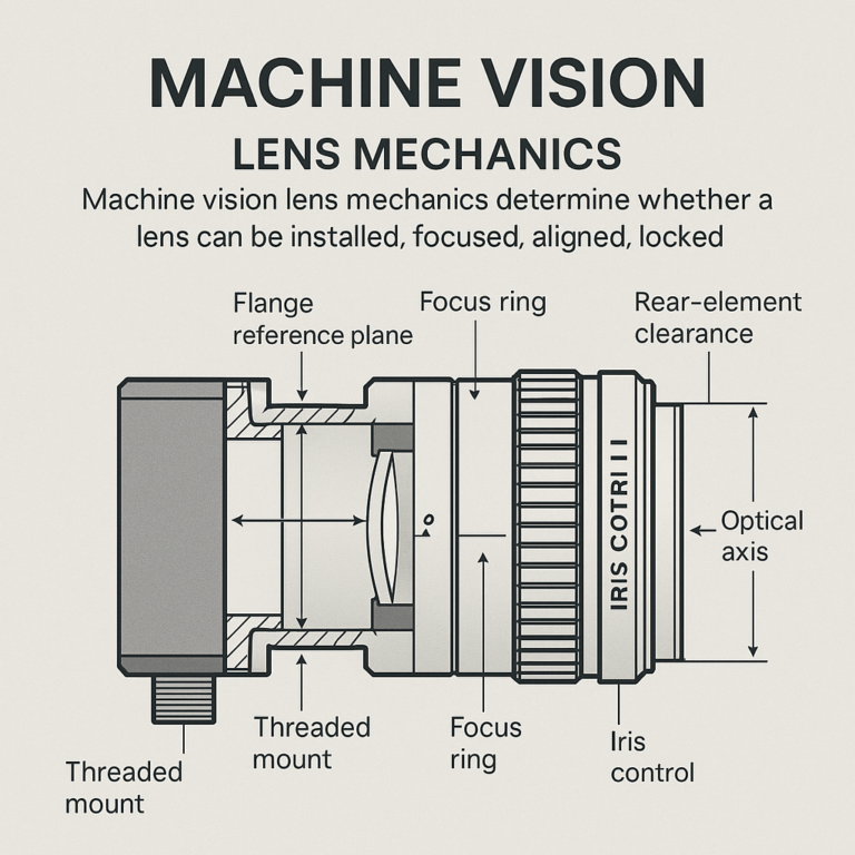
Machine Vision Lens Mechanics: Mounts, Alignment, and Barrels
12 min read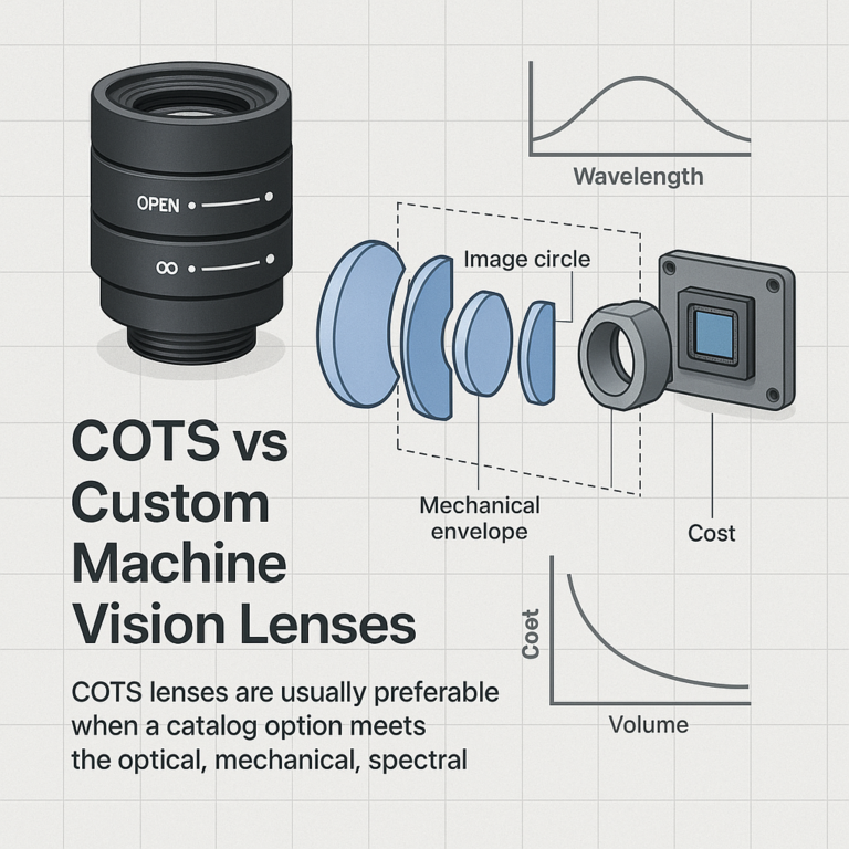
COTS vs Custom Machine Vision Lenses: Cost and Design Trade-Offs
10 min read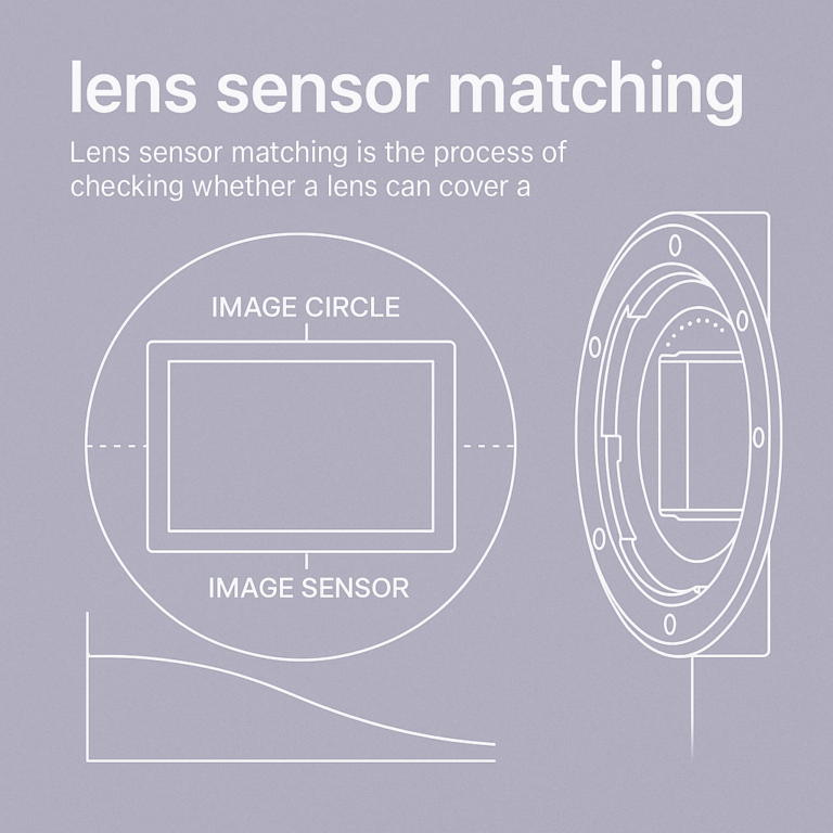
Lens Sensor Matching: Image Circle, Pixel Size and Mounts
8 min readAbout SUPERIOR OPTICS
SUPERIOR OPTICS specializes in CCTV lenses, machine vision optics, and custom optical solutions for security, industrial imaging, and specialty applications. We also provide professional lens selection and application support.