


Machine Vision Lens Mechanics: Mounts, Alignment, and Barrels
A mechanical integration guide to lens mounts, flange distance, barrel clearance, focus and iris controls, locking methods, vibration exposure, and sensor alignment.
Key Takeaways
Machine Vision Lens Mechanics should be reviewed as an interface stack, not reduced to matching a lens thread with a camera mount.
- Verify the mount thread, flange position, shoulder contact, engagement depth, and rear clearance before releasing a housing.
- Treat every adapter, spacer, filter, and retainer as part of the focus and alignment stack.
- Model the lens at both adjustment extremes, including rotating controls, rear-element travel, cables, and tools.
- Select focus and iris locks according to vibration exposure, calibration needs, and expected field service.
- Inspect image-plane alignment at operating focus and aperture rather than accepting thread compatibility as proof of performance.
The Short Answer
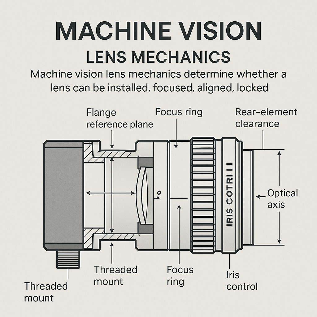
Machine Vision Lens Mechanics determine whether a lens can be installed, focused, aligned, locked, and kept stable in the intended enclosure. Integration depends on more than thread compatibility: flange position, shoulder geometry, thread engagement, barrel envelope, adjustment travel, rear clearance, sensor alignment, and vibration exposure all matter. Buyers should review the complete mechanical stack—including adapters, windows, filters, retainers, and housing datums—then verify focus and image-plane alignment on a representative prototype before production tooling is released.
Why Machine Vision Lens Mechanics Matter During Camera Integration
A lens can satisfy focal-length and sensor-coverage requirements yet still fail at the mechanical interface. The common failure paths are physical interference, a focus position outside available travel, controls that cannot be reached, movement after adjustment, and a sensor plane that is not sufficiently square to the optical system.
Mechanical constraints that can change optical performance
Lens-to-sensor position determines whether the intended focus condition is reachable. Decenter and tilt can also move the principal point or alter calibrated image characteristics, according to Commonlands’ focus and calibration guidance. For metrology, this makes mechanical movement a calibration issue as well as a packaging issue.
Common prototype failures: interference, lost focus range, movement, and sensor misalignment
A housing may clear the fixed barrel but collide with a rotating focus ring. A retainer may consume needed thread travel. An unlocked lens may shift under handling or vibration. These are predictable integration risks, although their acceptable limits depend on the lens, sensor, working distance, aperture, and measurement requirement.
What to confirm before finalizing a camera housing
Freeze the housing only after reviewing the mount datum, axial stack, maximum lens envelope, adjustment access, front accessories, rear projection, sensor position, and locking method. Use worst-case part dimensions when available; nominal CAD alone does not establish assembly clearance.
Machine Vision Lens Mechanical Integration Comparison
| Mechanical factor | What to verify | Integration risk if missed | Typical mitigation |
|---|---|---|---|
| Mount interface | Thread form, diameter, pitch, datum | Non-fit or unstable seating | Match drawings and inspect mating parts |
| Flange focal distance | Mount datum to sensor plane | Intended focus cannot be reached | Correct mount position or adapter stack |
| Thread engagement and shoulder | Engagement depth and seating face | Bottoming, looseness, or false datum | Add controlled relief or revise engagement |
| Barrel diameter and length | Full static and moving envelope | Housing interference | Increase clearance or select another barrel |
| Focus travel | Required position plus adjustment margin | Lost working-distance range | Prototype the complete axial stack |
| Iris mechanism | Lever, ring, motor, and tool access | Aperture cannot be set or serviced | Reserve radial and operator clearance |
| Locking method | Retention and service requirements | Focus or iris drift | Lock ring, set screw, retainer, or qualified adhesive |
| Alignment | Mount axis, sensor plane, datums | Uneven focus or calibration variation | Control datums and inspect the image plane |
| Rear clearance | Rear element and sensor-cover envelope | Contact or restricted focus travel | Section-view and end-stop checks |
| Vibration exposure | Excitation, shock, temperature, duty cycle | Adjustment movement or image shift | Ruggedized design and application-level validation |
Machine Vision Lens Mounts and Interface Compatibility
How do machine vision lens mounts affect integration?
Mount geometry sets the seating reference, available engagement, camera-side clearance, and nominal lens-to-sensor relationship. Adapter thickness and alignment add to that stack. A matching thread therefore does not prove that the lens will focus, clear the camera, cover the sensor, or remain coaxial.
Thread type, mount diameter, and thread engagement
C-mount and CS-mount use a nominal one-inch thread with 32 threads per inch. Their documented flange focal distances differ: 17.526 mm for C-mount and 12.526 mm for CS-mount. M12 lenses use a 12 mm threaded interface and are commonly focused by threading the barrel in or out, as summarized in this machine-vision mount reference.
Thread engagement must hold the assembly without letting the barrel bottom against an unintended feature. Buyers comparing interfaces can review M12, C-mount, and CS-mount interface compatibility before committing to a camera plate or adapter.
Mount shoulder position and available camera-side clearance
The shoulder or specified datum should seat before another lens feature contacts the camera. Check counterbores, protruding sensor covers, fastener heads, flex cables, and any locking screw that enters the thread region. The practical datum is the surface that actually controls assembly position.
When adapters introduce mechanical and alignment risk
A documented C-to-CS use case adds a 5 mm adapter because the two interfaces differ by 5 mm in flange focal distance. The reverse arrangement does not provide the space a CS lens needs on a C-mount camera. More generally, an adapter adds two interfaces, extra axial length, and additional opportunities for runout or tilt.
Flange Focal Distance, Back Focus, and Focus-Range Planning
What flange focal distance controls
Flange focal distance is measured from the mount reference plane to the sensor image plane. If the assembled sensor position differs from the lens’s expected geometry, the usable focus range shifts and the intended working distance may become unreachable.
Separating flange focal distance from lens back focal length
Flange focal distance is an interface dimension. Back focal length describes an optical-system distance and should not be substituted for the mount datum-to-sensor requirement. This distinction is especially relevant to board-level lenses, where focus is often established by thread position rather than a standardized flange plane. See M12 lens mechanical fit, including back focal length and clearance for the associated drawing checks.
How spacers, adapters, and retaining features affect focus travel
Engineering interpretation: each axial component changes the installed relationship between lens and sensor, even when it is not sold as an optical part. Add adapter thickness, shims, shoulders, retainers, and manufacturing variation into one stack-up. Then compare the stack’s extremes with the lens’s usable adjustment range.
Checking sensor clearance and rear-element movement
Inspect a section view at both focus limits. Include the rear barrel, any moving optical group, sensor cover glass, package features, and assembly tolerances. Clearance must be established from drawings or controlled samples; no universal safe gap is supported by the available sources.
Lens Barrel Construction and Housing Clearance
Lens barrel construction: fixed dimensions, moving groups, and external features
A barrel drawing should distinguish fixed bodies from moving focus groups, iris rings, levers, lock rings, motor housings, and connector exits. A single maximum diameter is insufficient when controls rotate or translate.
Diameter, length, and rotation-envelope checks
Create swept envelopes for every user-adjustable part. Check access for the tool or operator as well as the component itself. For an M12 barrel, include the axial positions needed to focus at the specified working-distance limits rather than modeling one nominal thread position.
Front clearance for filters, protective windows, and illumination hardware
Front hardware can conflict with the lens nose, filter thread, focus ring, or field illumination. A protective window also becomes part of the optical path, so changing its material or thickness calls for optical review rather than a clearance-only signoff. This last point is engineering inference and must be validated for the selected lens.
Selecting barrel geometry for compact OEM enclosures
Compactness is not simply the shortest catalog lens. Compare installed length, maximum diameter, adjustment access, cable bend space, filter retention, and assembly sequence. A slightly longer fixed-focus barrel may be easier to lock and inspect than a shorter design with inaccessible controls.
Focus Adjustment, Iris Mechanisms, and Locking Methods
Manual focus, fixed focus, and locking focus designs
Set-and-lock manual focus is a practical default where working geometry remains stable. A locked lens also preserves lens-to-sensor distance used in pixel-to-world calibration. Motorized focus is justified when operating distance changes, but movement can change calibrated intrinsic parameters and may require qualified positions or recalibration.
Iris mechanism options and their mechanical implications
An adjustable iris requires radial clearance for a ring, lever, cable, or motor. Stopping down can widen the sharp zone but reduces light, a trade-off documented in the Commonlands guidance. Fixed-aperture designs remove the control envelope but do not allow aperture adjustment after installation.
Set screws, lock rings, adhesive locking, and retaining hardware
A set screw is compact but introduces a local contact point. A lock ring uses axial space and requires tool access. Adhesive can suit a factory-set assembly but complicates later adjustment. Retaining hardware should clamp against an intended surface, not distort a focus ring or moving barrel. Final selection requires application-specific retention testing.
How to prevent vibration-induced lens movement
Start with a positive seating datum and a lock that acts on the intended adjustment feature. Eliminate cable loads on motorized controls, document tightening procedures, and test at operating focus. Commercial ruggedized and stabilized variants exist for shock-, vibration-, and alignment-sensitive systems, as shown in Schneider-Kreuznach’s C-mount configurations. Broader qualification should follow the expected vibration-resistant imaging system environmental design, not a generic retention assumption.
Machine Vision Lens Alignment and Sensor Tilt Tolerance
Machine vision lens alignment: optical axis, mount axis, and sensor plane
These references are related but not automatically identical. The mount axis comes from manufactured mechanical features; the sensor plane comes from the camera assembly; the optical axis depends on lens construction and seating. Machine Vision Lens Mechanics become measurable when drawings identify which datums control each relationship.
How sensor tilt tolerance affects edge sharpness and measurement consistency
Engineering interpretation: sensor tilt makes opposite sides of the image reach best focus at different axial positions. Whether that difference is acceptable depends on depth of field, pixel size, aperture, field position, and the inspection’s measurement limits. A universal sensor tilt tolerance cannot be responsibly specified from the supplied evidence.
Decenter, tilt, and stack-up errors in camera assemblies
Mount runout, adapter faces, holder flatness, sensor placement, and barrel seating can accumulate. Commonlands documents that decenter or tilt can shift the principal point; in calibrated systems, this can affect more than visible sharpness. Evaluate the assembled chain rather than assigning the entire alignment budget to one component.
Using mounting datums and inspection points to control alignment
Reference the camera housing, lens mount, and sensor carrier to controlled datums. Useful inspection points include mount-face position, thread or bore axis, sensor-plane location, and image-based focus uniformity. The drawing controls geometry; the image test determines whether the assembled result is fit for the application.
Installation Tolerances and Prototype Verification Checklist
Mount and thread verification
- Confirm interface designation, pitch, engagement, shoulder seating, and tightening method.
- Inspect mating parts from representative production processes.
- Verify that adapters cannot bottom out or seat on unintended features.
Focus, clearance, and moving-part verification
- Focus at minimum, nominal, and maximum required working distance.
- Check rear and front clearance at all adjustment limits.
- Exercise focus, iris, motors, filters, windows, cables, and required tools.
Vibration and locking verification
- Record focus and iris settings before exposure.
- Apply the application’s defined vibration, shock, temperature, and handling profile.
- Recheck retention, image position, focus uniformity, and calibration status afterward.
Image-plane alignment verification before production release
Use a target and method appropriate to the inspection task. Compare center and edge focus, rotate components where diagnostic separation is useful, and record settings. Acceptance limits must come from system performance requirements; the reviewed sources do not establish a universal pass/fail tolerance.
Choose the Right Mechanical Lens Configuration for Your System
When a standard lens interface is sufficient
A standard interface is usually defensible when the mount, focus range, sensor coverage, barrel envelope, adjustment access, alignment, and retention method all pass prototype verification without special machining.
When a custom barrel, mount, or optical assembly is justified
Customization becomes reasonable when the standard barrel collides with the enclosure, focus cannot be locked accessibly, alignment errors consume the system budget, environmental retention is inadequate, or production assembly needs a controlled fixed-focus position. Compare that work with the tooling and lifecycle cost of modifying the camera housing.
Information to provide when requesting an integration review
Supply the sensor format and mount, working-distance and focus range, housing drawing, available envelope, flange and rear-clearance constraints, environmental conditions, and required focus or iris controls. SUPERIOR can review these inputs against available machine vision lens and optical lens assemblies and identify where a custom mechanical configuration may warrant evaluation.
Frequently Asked Questions
Can a lens adapter change the usable focus range of a machine vision camera?
Yes. An adapter changes the axial relationship between the lens mount and sensor and may also add alignment error. If its optical thickness does not produce the interface geometry expected by the lens, the focus range can shift or disappear. Include the adapter’s tolerances when checking the complete stack.
What mechanical dimensions should be included in a lens-to-housing clearance drawing?
Include the mount datum, thread or bore specification, shoulder position, installed barrel length, maximum diameter, moving-part envelopes, rear projection, focus and iris travel, lock features, connector exits, front accessories, and tool access. Show worst-case axial and radial positions rather than only the nominal focused configuration.
When should an OEM use a custom lens barrel instead of modifying the camera enclosure?
Use a custom barrel when enclosure changes would compromise packaging, tooling, sealing, assembly access, or multiple product variants, and when lens volume justifies dedicated engineering. The decision should compare lifecycle cost and validation effort. A custom barrel still requires optical, tolerance, retention, and environmental qualification in the final camera.
How can a protective window affect lens installation space and focus adjustment?
A window and its retainer consume axial or radial space and may obstruct the lens nose, filter thread, focus ring, or illumination. Because the window also enters the optical path, changing its material, thickness, tilt, or spacing may require optical reassessment and refocusing, not merely an updated housing clearance check.
What information should be shared with a lens supplier before building a prototype?
Share sensor dimensions, mount interface, required field of view, working-distance range, aperture needs, housing CAD, installation envelope, sensor position, rear clearance, filters or windows, adjustment access, locking preference, and environmental exposure. Also identify calibration and measurement requirements so movement, tilt, and focus repeatability can be assessed appropriately.
Topics
Related Articles
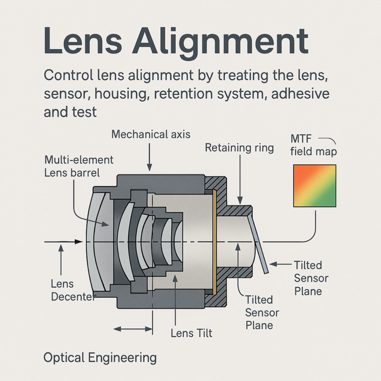
How to Control Lens Alignment, Tilt, Decenter, and MTF Degradation
11 min read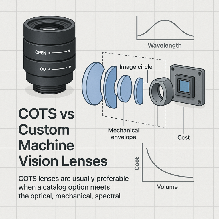
COTS vs Custom Machine Vision Lenses: Cost and Design Trade-Offs
10 min read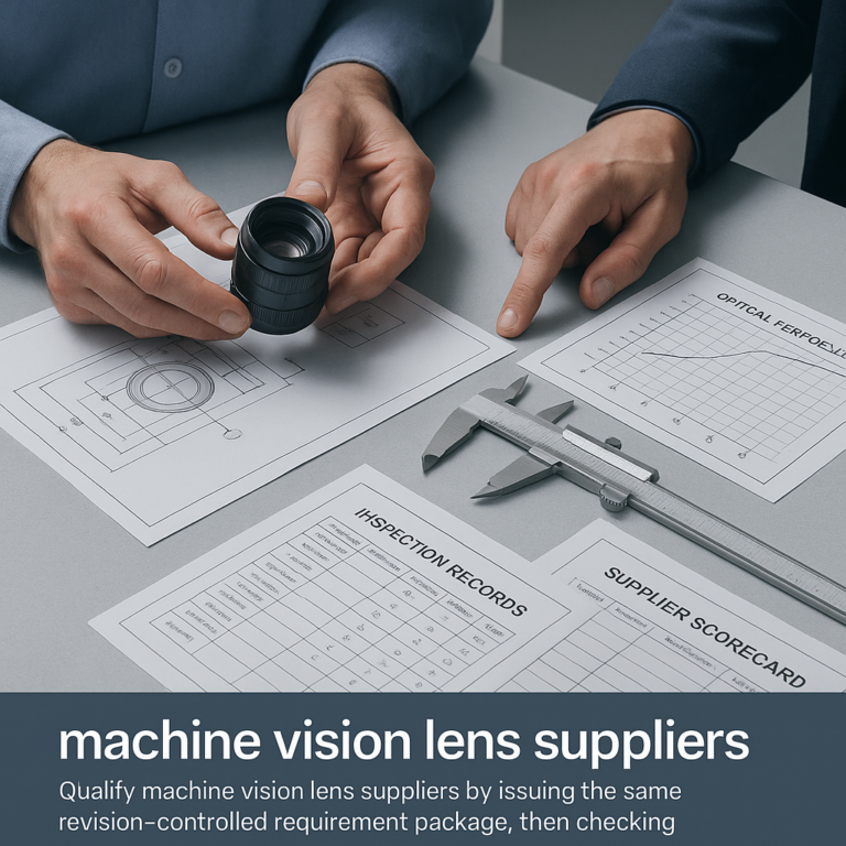
How to Qualify and Compare Machine Vision Lens Suppliers for OEMs
11 min readAbout SUPERIOR OPTICS
SUPERIOR OPTICS specializes in CCTV lenses, machine vision optics, and custom optical solutions for security, industrial imaging, and specialty applications. We also provide professional lens selection and application support.