


Chief Ray Angle and Image Circle: Matching Lenses to Sensors
A practical engineering guide to evaluating ray-angle acceptance, sensor coverage, corner MTF, optical stack and mount geometry before committing to a lens.
Key Takeaways
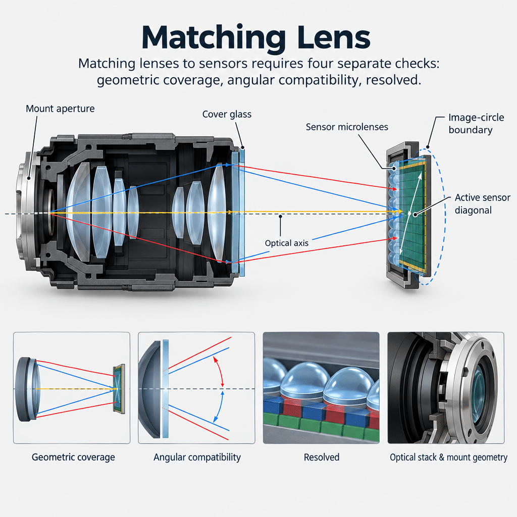
A lens is compatible only when geometric coverage, angular response, usable edge detail and mechanical integration all meet the camera’s operating requirements.
- Compare the full Chief Ray Angle curve with the sensor’s angular-response or microlens guidance, not just a single corner value.
- Use exact active width and height to calculate sensor diagonal; optical-format labels are insufficient for coverage decisions.
- Treat image-circle diameter as an initial screen because it does not establish corner brightness, color uniformity or MTF.
- Review the real cover-glass, filter and mount stack before approving focus range or peripheral performance.
- Validate the assembled camera at center, edge and corner under the intended aperture, spectrum, focus and working distance.
The Short Answer
Matching lenses to sensors requires four separate checks: geometric coverage, angular compatibility, resolved detail and mechanical fit. Chief Ray Angle is the angle between the optical axis and a chief ray at the sensor plane, and its field-dependent profile should align with the sensor’s microlens response. The image circle must cover the active sensor diagonal, but coverage alone cannot guarantee corner brightness or sharpness. Pixel size, edge MTF, cover glass, filters, back-focus clearance and clear apertures must also be assessed, then verified on the assembled camera.
What Is Chief Ray Angle?
CRA describes the angle between the optical axis and the chief ray where that ray reaches the image plane. The angle normally varies with image height: rays near the optical center and those reaching a corner do not necessarily arrive at the same inclination. Consequently, a CRA-versus-image-height curve is more useful than one headline value, according to this technical explanation of lens and sensor CRA mismatch.
The sensor is not simply a flat, angle-neutral collector. Its microlenses direct incident light toward the photosensitive region, and different microlens configurations can be designed for different angular profiles. Even variants based on similar sensor silicon may therefore have different acceptance behavior.
A Chief Ray Angle mismatch occurs when the lens’s ray profile does not align adequately with that sensor response. Possible symptoms include corner signal loss, color shading, crosstalk and reduced contrast. Those symptoms are not exclusive proof of CRA mismatch; relative-illumination roll-off and mechanical clipping can create overlapping effects.
Compact M12 designs deserve particular scrutiny because coverage, angular response and edge detail must coexist within limited mechanical space. This guide to chief ray angle compatibility for M12 lens resolution expands on that interaction.
How Does Image Circle Affect Sensor Coverage?
Image circle determines whether the lens projects an image across the complete active area. As a geometric screen, the specified usable image-circle diameter should equal or exceed the active sensor diagonal. Calculate the diagonal from active dimensions rather than relying on an optical-format label:
Sensor diagonal = √(active width² + active height²)
Illustrative calculation: an assumed 6.4 mm × 4.8 mm active area has an 8.0 mm diagonal. A lens specified for less than 8.0 mm cannot geometrically cover its corners. This arithmetic does not establish how much margin a real design needs.
Nominal coverage still says little about what happens near the boundary. The image-circle specification may be based on illumination, MTF or another supplier-defined criterion, under particular aperture, wavelength and conjugate conditions. Those conditions need to match the application. The distinction becomes especially consequential with large-sensor machine vision lenses with image circle and edge quality.
Keep three checks separate:
- Coverage: Does projected imagery reach every active pixel?
- Relative illumination: Is peripheral signal adequate and sufficiently uniform?
- Resolution: Does edge and corner MTF preserve task-relevant contrast?
A larger nominal circle can help coverage screening, but it does not automatically solve angular mismatch, field curvature, natural falloff or mount clipping. The image-circle compatibility guidance likewise treats coverage, CRA, mechanical fit and corner quality as separate decisions.
How to Evaluate Lens Sensor Compatibility Before Prototyping
Begin with controlled inputs. For the lens, request usable image circle, CRA by image height, center-to-corner MTF at the intended aperture, relative illumination, spectral conditions, back focal requirements and mechanical drawings. For the camera, collect exact active dimensions, pixel size, microlens or angular-response guidance, cover-glass and filter details, mount datum, clear apertures and focus adjustment range.
The broader process for lens sensor matching for image circle, pixel size, and mounts explains why these checks should not be collapsed into one megapixel or format rating.
Compare CRA curves over the active field. If the sensor manufacturer provides no angular-response data, compatibility remains unresolved rather than confirmed. Sample testing or optical simulation is then the defensible next step.
Pixel size is also not a stand-alone lens specification. Evaluate lens MTF at spatial frequencies relevant to the task and at the actual field positions. A security camera seeking recognizable peripheral detail, for example, may set a different contrast threshold from a metrology system locating an edge. The acceptance criterion belongs to the application, not the pixel count alone.
Finally, overlay the mechanical stack. A lens may cover the sensor optically yet have rays clipped by a mount bore, retainer, filter holder or camera chamber. Rear protrusion and available back-focus travel can also prevent installation or focus.
Common Lens-Sensor Mismatch Symptoms and Their Likely Causes
Dark corners: First distinguish smooth illumination roll-off from abrupt clipping. Smooth, aperture-dependent falloff may originate in the optical design; hard or asymmetric shading points more strongly toward physical obstruction. CRA mismatch can also reduce corner signal, particularly when shading includes a color component.
Color shading: Field-dependent color variation can result when sensor response changes with incidence angle. It is evidence for investigating lens-to-microlens alignment, but not a diagnosis by itself. Illumination spectrum, filters and the image-processing pipeline must remain controlled during comparison.
Soft edges: Likely candidates include inadequate off-axis MTF, field curvature, defocus introduced by the sensor stack or a lens used outside its intended conjugate. Refocusing the center may not recover the corners if the underlying issue is field-dependent.
Mechanical shading: Mount throats, barrel bores, retainers and filters can intercept off-axis rays. Inspect the complete ray path rather than approving the nominal mount standard alone.
Flat-field correction may improve apparent uniformity, but it cannot recover optical detail or signal-to-noise performance that the camera never captured. That makes correction a calibration decision, not a substitute for compatible optics.
Compatibility Table: Match the Lens, Sensor, and Mount
The following table separates initial screening data from evidence needed for approval.
| Compatibility Factor | Lens Data to Confirm | Sensor or Camera Data to Confirm | What a Match Looks Like | Risk When Mismatched |
|---|---|---|---|---|
| Chief Ray Angle | CRA distribution from center to corner | Angular response and microlens behavior | Ray angles remain within the usable sensor response across the active area | Color shading, corner signal loss, uneven brightness |
| Image circle | Usable diameter and edge-performance criterion | Active width, height, diagonal and corner locations | Full active area is covered with acceptable peripheral performance | Dark or unusable corners |
| Resolution and pixel size | Center and corner MTF at operating aperture | Pixel size and task contrast requirement | Contrast supports required detail at specified field points | Soft edges and measurement error |
| Sensor stack | Cover-glass and filter design assumptions | Actual thicknesses, materials and placement | Focus and field performance remain acceptable with the real stack | Focus shift and field-dependent blur |
| Mount geometry | Rear protrusion, back-focus range and clear aperture | Mount datum, chamber, filters and adjustment travel | No interference or ray clipping; focus remains reachable | Mechanical vignetting or inability to focus |
Engineering inference: where a supplier cannot disclose CRA, peripheral MTF or the criterion behind its image circle, the risk has not disappeared; it has shifted into simulation and sample-validation work.
A Practical Workflow for Matching Lenses to Sensors
- Set the imaging requirement. Record field of view, working distance, target detail, spectrum, aperture range, exposure constraints and acceptable center-to-corner variation.
- Calculate the active diagonal. Screen out lenses whose usable image circle cannot cover the exact active area.
- Review peripheral evidence. Compare relative illumination and MTF under relevant wavelength, aperture and conjugate conditions.
- Check angular response. Overlay lens CRA by image height with sensor guidance. Mark missing data as an open risk.
- Model the stack-up. Include cover glass, IR-cut or pass filters, mount throat, retainers, tolerances and focus travel.
- Test the assembled configuration. Capture controlled center, edge and corner results for brightness, color uniformity and task-relevant resolution before volume approval.
For elongated or non-standard formats, use a workflow specific to line scan lens selection for large sensor coverage, because sensor length, magnification and field uniformity can dominate the screening decision.
A useful approval record names the exact lens revision, sensor variant, filter stack, aperture, focus setting, wavelength or illuminant, working distance and processing state. Otherwise, a passing result can be difficult to reproduce after a component or configuration change.
When a Custom Optical Assembly Is the Better Path
A custom assembly becomes reasonable when standard lenses cannot simultaneously satisfy image circle, CRA profile, edge MTF, spectral transmission and package constraints. It can also be justified when mechanical interfaces force clipping or when the required sensor stack differs materially from a catalog lens’s design assumptions.
That decision is an engineering trade-off, not an automatic upgrade. Custom development adds specification, validation and production-control work. Before starting, define measurable acceptance criteria at center, edge and corner, plus environmental, spectral, focusing and interface requirements.
Applications extending beyond visible light need wavelength-specific analysis rather than an assumption that visible focus and coatings will transfer unchanged. For surveillance projects, the available infrared camera lenses for night-surveillance imaging provide a relevant starting category, subject to sensor and system-level verification.
For a lens-sensor compatibility review, provide the sensor model or active area, diagonal, pixel size, optical stack, mount drawing, field of view, working distance, spectral band, aperture range and corner-performance target. That package allows a standard-lens recommendation or custom feasibility review to address the actual integration risks.
Frequently Asked Questions
Can a lens cover a sensor diagonal but still produce poor corner image quality?
Yes. An adequate image circle establishes geometric coverage only. Corner quality may still be limited by relative-illumination roll-off, CRA mismatch, weak off-axis MTF, field curvature, the sensor cover-glass stack or mechanical clipping. Review brightness, color response and task-relevant resolution separately at the operating aperture and wavelength.
Does a larger image circle always reduce vignetting?
No. A larger specified circle may provide geometric coverage margin, but it does not eliminate natural illumination falloff, aperture-dependent optical vignetting, sensor angular-response mismatch or clipping inside the mount. Check how the supplier defined the usable circle and inspect relative illumination and mechanical clear apertures under application conditions.
Why can the same lens perform differently on two sensors with similar dimensions?
Because physical size is only one compatibility variable. The sensors may use different pixel sizes, microlens offsets, angular-response profiles, cover-glass thicknesses, filter stacks or active-area locations. Camera processing can also alter visible shading. Compare the exact sensor variants and test with equivalent processing settings.
How do cover glass thickness and filters affect lens sensor compatibility?
They alter the optical stack through which converging rays travel before reaching the pixels. A stack that differs from the lens’s design assumption can shift focus or degrade field-dependent performance, especially toward the corners. Supply thickness, material and placement data, then validate the complete camera rather than the bare lens.
What information should an OEM provide when requesting a lens-sensor compatibility review?
Provide the sensor model, active width and height, pixel size, angular-response guidance, cover-glass and filter stack, mount drawing, available back focus, field of view, working distance, spectral range and aperture. Add measurable center, edge and corner requirements for illumination, color uniformity, distortion and resolution.
Topics
Related Articles

How to Qualify a Custom Lens Manufacturer for Global OEM Programs
10 min read
Custom Lens Development: From Feasibility to Mass Production
11 min read
What lens is used in CCTV?
11 min readAbout SUPERIOR OPTICS
SUPERIOR OPTICS specializes in CCTV lenses, machine vision optics, and custom optical solutions for security, industrial imaging, and specialty applications. We also provide professional lens selection and application support.