

M12 Lens Resolution and CRA: Matching Optics to the Camera Sensor
A procurement-focused method for translating sensor and application requirements into testable MTF, field-performance and chief-ray-angle criteria.
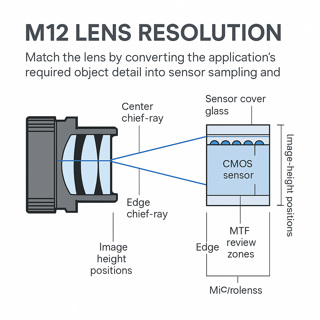
Key Takeaways
A defensible M12 Lens Resolution review separates sampled detail, field-dependent optical performance and chief-ray-angle compatibility instead of relying on a megapixel label.
- Translate the application’s smallest required detail into a sensor, field-of-view and working-distance requirement before comparing lenses.
- Request MTF evidence at agreed spatial frequencies and at center, mid-field and corner positions under production-representative conditions.
- Compare the lens CRA profile with the sensor’s angular-response guidance; image-circle coverage alone is not an acceptance test.
- Evaluate visible, near-infrared and day-night configurations separately when their spectra, filters or focus conditions differ.
- Put evidence gaps, sample tests, production variation and pass/fail thresholds into the RFQ before approving tooling or volume orders.
The Short Answer
Match the lens by converting the application’s required object detail into sensor sampling and field requirements, then ask for MTF results at relevant spatial frequencies, image positions, aperture, wavelength and focus distance. Review chief ray angle separately: compare the lens-side CRA profile with the sensor manufacturer’s angular-response guidance across image height. Image-circle coverage does not establish edge resolution or angular compatibility. Approve samples only after tests with the intended sensor stack, illumination, filters, mount and working distance meet documented limits for detail, shading, color response and production variation.
An M12 lens is commonly identified by its 12 mm threaded interface, and focus can be adjusted by changing its threaded position in the mount. A manufacturer’s M12 lens selection guide also identifies sensor size, resolution, field of view, aperture, near-infrared sensitivity and operating temperature as selection considerations.
Those checks are necessary but not sufficient for sample approval. Resolution review asks whether the lens delivers adequate field-dependent contrast for the sensor and task. CRA review asks whether rays reach the sensor within its supported angular response. Procurement teams should keep the two evidence trails separate.
M12 Lens Resolution and CRA Compatibility Review Checklist
Use this checklist to request resolution and chief-ray-angle evidence separately before approving an M12 lens sample.
| Review area | Required sensor data | Required lens supplier evidence | Required test conditions | Acceptance criteria |
|---|---|---|---|---|
| M12 Lens Resolution target | Pixel pitch, pixel count, active area, required object detail, field of view and working distance | MTF curves or measured results at nominated spatial frequencies | Agreed focus distance, aperture, spectrum and temperature where relevant | Each required field position meets the documented MTF or task-level threshold |
| Field consistency | Active dimensions and required image-quality zones | Center, mid-field and corner MTF; sagittal and tangential results where needed | One measurement method and matched optical settings | No required zone falls below its assigned limit |
| M12 lens CRA | Sensor CRA acceptance or angular-response guidance, plus available microlens and stack information | Lens CRA profile by image height or field angle | Production-representative cover glass and filters | Lens profile stays within the documented sensor acceptance envelope |
| Shading and color risk | Spectral range, color-filter configuration and available correction limits | Relative-illumination data, CRA data and supporting simulation or images | Intended illumination, aperture, exposure settings and stack | System test remains within agreed edge-response, shading and color limits |
| Sample and production validation | Final module configuration and application test method | Sample report, production controls and agreed lot evidence | Representative target, mount tolerance, distance and illumination | Samples and production parts pass optical and mechanical criteria |
Start M12 Lens Resolution Selection With the Sensor and Application Requirement
Begin with the detail that must survive the imaging chain
“High resolution” is not a purchasing requirement. State the feature, defect, character or subject detail the camera must distinguish, where it appears in the field, and under what motion and illumination conditions. Record field of view and working distance because a lens acceptable for overview surveillance may fail a machine-vision task using the same sensor.
For security systems, also separate detection, recognition and evidentiary detail expectations rather than assigning one vague quality target. Buyers comparing CCTV security camera lens options for sensor-matched designs should carry those task definitions into the lens inquiry.
Build a controlled sensor record
Attach the sensor part number and revision, pixel pitch, active pixel count, active dimensions and intended readout mode. Include the module’s cover glass, IR-cut filter or bandpass filter, expected lens-to-sensor spacing and any sensor-vendor guidance on angular response.
Treat “optical format” as a screening label, not dimensional evidence. Use the active sensor diagonal and required image area when checking coverage. Likewise, a lens megapixel rating does not disclose test frequency, aperture, focus distance, wavelength or corner performance unless the supplier provides those conditions.
Translate Sensor Pixel Pitch and Lens Resolution Into MTF Requirements
Pixel pitch indicates the sensor’s sampling scale, but it does not by itself establish the detail required in object space. The review must connect pixel pitch to active image dimensions, field of view and the application feature. A deeper treatment of sensor pixel pitch and lens resolution can support that calculation.
For M12 Lens Resolution sourcing, ask the camera or optical team to nominate the spatial frequencies at which evidence is required. The RFQ should state whether values are design predictions, supplier measurements or measurements from production-representative samples. Curves without a defined frequency axis and test configuration are not comparable evidence.
Field position changes the buying decision
Center-only data can conceal the region that controls acceptance. Identify field positions as image height, normalized field or sensor coordinates, then mark the zones used by the application. A barcode near one edge, for example, makes that edge a primary acceptance zone rather than a secondary reference point.
Request center, mid-field and corner results at the intended aperture and focus distance. Sagittal and tangential curves are useful where directional detail or off-axis behavior matters, but the RFQ must use the supplier’s documented terminology and test method.
Keep system losses visible. Motion, defocus, mounting tilt, low signal, illumination geometry and processing can reduce measured task performance even when the lens report passes. Lens MTF evidence therefore screens the optic; a camera-level trial validates the assembled system.
M12 Lens MTF Requirements Suppliers Can Quote
A usable requirement contains five elements: spatial frequency, field position, spectrum, aperture and focus condition. Add temperature only when the application has a defined environmental range and the resulting focus or performance change will be tested.
Avoid mixing curves obtained under different conditions. An infinity-focused broadband curve and a close-working-distance monochromatic curve do not support a direct pass/fail comparison. Ask suppliers to identify whether results are nominal simulations, measured samples or guaranteed production limits.
Production language matters too. A prototype result does not define lot acceptance. The purchase specification should identify sampling method, permitted variation, retest rules and which characteristics require supplier control. Where tolerances could shift focus or decenter performance, include the final mount and focus-locking process in validation.
Evaluate M12 Lens CRA and Chief Ray Angle Compatibility
CRA describes the direction of the chief ray at the sensor side as a function of field position. For sourcing purposes, request two datasets: the lens CRA profile and the sensor manufacturer’s CRA acceptance or angular-response guidance. If the sensor vendor does not publish an envelope, record that absence as an unresolved risk rather than declaring compatibility.
Potential failure modes to investigate include edge shading, reduced corner response and field-dependent color variation. These outcomes must be checked on the intended sensor because microlenses, color filters, cover glass, correction settings and spectrum are parts of the camera system. The related review of chief ray angle compatibility and corner MTF performance explains why coverage, illumination and edge detail need separate evidence.
Coverage and angular compatibility answer different questions
An image circle indicates whether the lens projects light over the required area. It does not, by itself, establish edge MTF, relative illumination or sensor angular acceptance. A lens can therefore pass a geometric coverage screen while remaining unapproved for corner performance.
Day-night and near-infrared cameras need condition-specific evidence. Ask for the wavelength band, filter stack, aperture and focus setting used for every comparison. Buyers can use these infrared camera lens considerations for wavelength-specific testing when defining a separate IR test state.
Run Separate Resolution and CRA Reviews Before Ordering Samples
The resolution review should map every application zone to an MTF or task-level requirement. The CRA review should map lens field angle or image height to the sensor’s angular-response information. Do not collapse both into a single “sensor compatible” checkbox.
Before samples ship, reconcile test conditions with the production stack. Cover glass thickness, filters, aperture, focus distance, illumination spectrum and mount position should either match production or be listed as deviations. This prevents a nominal pass from being carried into a materially different assembly.
A simple decision status helps procurement:
- Pass: evidence covers all required fields and conditions, and stated limits are met.
- Conditional: available evidence is acceptable, but named camera-level tests remain open.
- Hold: the lens or sensor profile is missing, conditions differ, or no acceptance threshold exists.
Build the Camera Sensor Matching Evidence Package
The approval file should contain the sensor datasheet and revision, module stack drawing, active mode, application geometry, spectrum and environmental conditions. Add the lens drawing, MTF and CRA submissions, relative-illumination information, sample reports and focus or mounting instructions.
Maintain an unresolved-risk log. Each entry needs an owner, closure test and decision date. Typical entries include unavailable sensor CRA guidance, simulated rather than measured corner data, an untested IR state or unknown production variation.
Optical simulation is appropriate when profiles are available but hardware is not, or when stack changes must be evaluated before tooling. Prototype testing remains necessary where supplier documentation is incomplete or the pass criterion is task-specific. A custom optical assembly becomes a sourcing option when standard parts cannot satisfy the combined mechanical, spectral, field and production requirements.
Common M12 Camera Sensor Matching Mistakes
- Accepting a megapixel label without its spatial frequency and test conditions.
- Treating image-circle diameter as proof of corner resolution or CRA acceptance.
- Comparing curves measured at different apertures, distances or spectral bands.
- Ignoring the sensor’s microlenses, cover glass, filters and correction settings.
- Testing visible operation but assuming the same focus and field response in near-infrared.
- Ordering samples before assigning pass/fail limits to center, mid-field and corner zones.
The commercial consequence is usually ambiguity rather than an immediate optical failure: suppliers quote different assumptions, sample comparisons become subjective, and production acceptance cannot be traced to the original requirement.
Turn the Review Into an RFQ and Purchase Specification
Write the RFQ around measurable submittals. Name the sensor, active mode, required image area, application geometry, spatial frequencies, field positions, aperture, spectrum, working distance and focus method. Request lens CRA and sensor-side compatibility evidence as a separate line item.
Then define the approval sequence: document review, sample test, deviation closure and production acceptance. The guide to how to match an M12 lens to a camera sensor in an RFQ provides a structure for moving these optical decisions into purchasing controls.
Do not approve tooling or volume production merely because samples produce an acceptable image under an informal setup. Record the target, illumination, software state, mount tolerance and acceptance calculation so the result can be repeated.
For a sensor-matching review, provide the sensor datasheet, pixel pitch, active area, field of view, working distance, spectrum, smallest required object detail and available CRA guidance. Ask the lens supplier to identify evidence gaps before selecting or quoting samples.
Frequently Asked Questions
What sensor information is needed before requesting M12 lens MTF data?
Provide the sensor part number, pixel pitch, active pixel count, active dimensions, readout mode and intended image-quality zones. Include field of view, working distance, required object detail, wavelength band, cover glass and filters. The lens supplier also needs the intended aperture, focus condition and any relevant temperature range.
How should an OEM specify field positions for an M12 lens resolution review?
Use image height, normalized field or sensor coordinates, and include a diagram showing required zones. Request center, intermediate and corner results, but add any task-specific location where detail matters. Keep aperture, focus distance, spectrum and measurement method constant so results from different field positions remain comparable.
Can an M12 lens cover a sensor image circle but still produce corner shading?
Yes. Image-circle coverage only establishes that the projected image reaches the required sensor area. It does not establish relative illumination, CRA compatibility, color uniformity or corner MTF. Evaluate those characteristics separately with supplier data and a production-representative camera test before accepting the lens for edge-critical imaging.
What test conditions should be included when requesting a lens CRA profile?
Request CRA by image height or field angle and identify the sensor-side reference plane, focus distance, optical configuration and wavelength band. The camera review should also document cover glass, IR-cut or bandpass filters, aperture and sensor stack. Ask the supplier to distinguish simulated data from measured results.
Should CRA compatibility be checked differently for visible and infrared camera systems?
Yes, when the operating bands, filters, focus settings or sensor response differ. Define separate visible and infrared test states with their illumination spectra, aperture and camera stack. Compare the available profiles for each state, then test edge response, shading and focus on the intended module rather than assuming one result transfers.
Topics
Related Articles
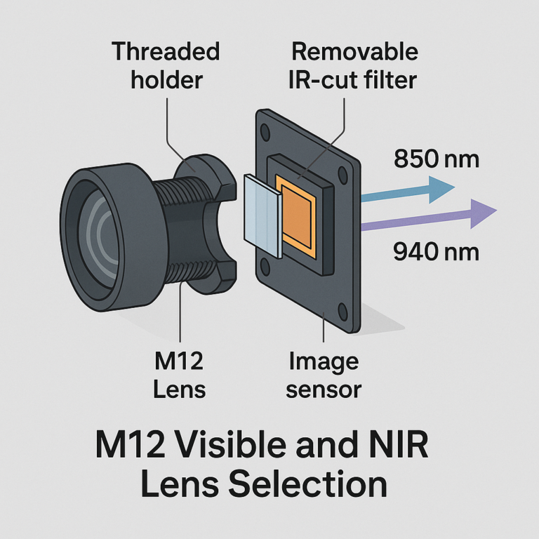
M12 Visible and NIR Lens Selection: Wavelengths and Filter Choices
11 min read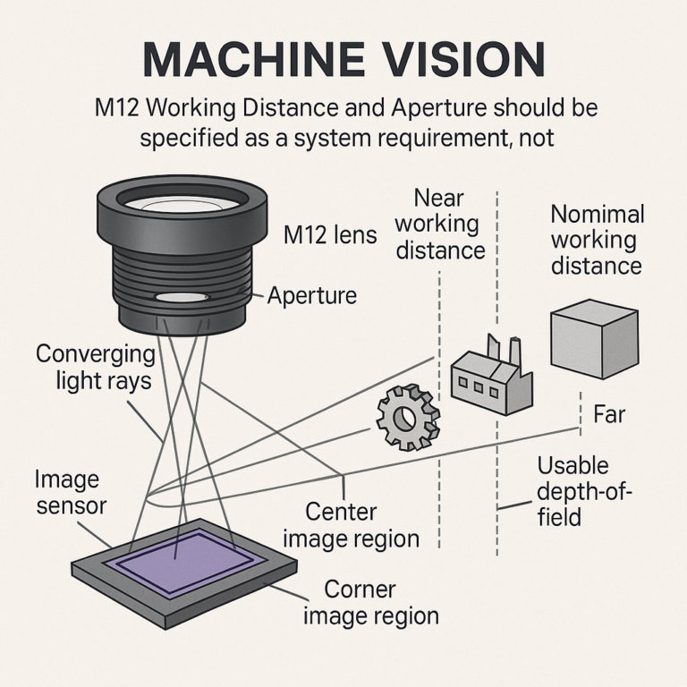
M12 Working Distance and Aperture: Specifying Usable Depth of Field
11 min read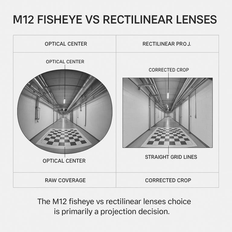
M12 Fisheye vs Rectilinear Lenses: Matching Coverage to Camera Tasks
10 min readAbout SUPERIOR OPTICS
SUPERIOR OPTICS specializes in CCTV lenses, machine vision optics, and custom optical solutions for security, industrial imaging, and specialty applications. We also provide professional lens selection and application support.