

Line Scan Lens Selection for Large Sensors and Reflective Parts
A calculation-led guide to matching line-sensor length, pixel pitch, scan width, image-circle coverage, working distance, focus tolerance, and reflective-part illumination.
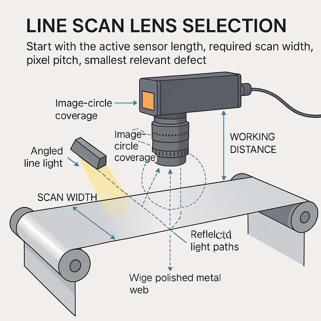
Key Takeaways
A defensible Line Scan Lens Selection starts with the required scan width and defect size, then tests whether the complete camera, lens, lighting, and conveyor geometry can preserve that requirement in production.
- Calculate magnification from active sensor length divided by object-side scan width before comparing focal lengths.
- Convert sensor pixel pitch into object-side pixel size, but set the required pixels per defect through application testing.
- Treat nominal sensor coverage as an initial filter; edge resolution and relative illumination must also pass across the active line.
- Validate focus at the nearest, nominal, and farthest expected part positions rather than relying on a single working distance.
- For reflective parts, evaluate lens placement and illumination together on representative surfaces because coverage alone cannot establish defect visibility.
The Short Answer
Start with the active sensor length, required scan width, pixel pitch, smallest relevant defect, and available working distance. Calculate magnification as sensor length divided by scan width, then divide pixel pitch by magnification to obtain object-side pixel size. Screen lenses for full sensor coverage, but approve one only after checking edge resolution, relative illumination, distortion, focus tolerance, and mechanical clearance. Reflective parts require a joint lens-and-lighting trial using representative finishes, defect types, orientations, and conveyor height variation.
Line Scan Lens Selection can look correct in a catalog and still fail at the ends of the sensor, at a different conveyor height, or on a polished surface. The procurement question is therefore not simply whether a lens fits the mount. It is whether the optical system preserves usable sampling and contrast over the full production envelope.
A practical eight-step sequence is:
- Define scan width and the smallest defect or feature that matters.
- Record active sensor length, pixel count, pixel pitch, and spectral range.
- Calculate magnification and object-side pixel size.
- Establish the algorithm’s required samples across the target defect.
- Verify usable image-circle coverage and edge performance.
- Check working distance, aperture, depth variation, and clearance.
- Test lighting and viewing geometry on representative parts.
- Freeze the validated focus, aperture, orientation, and acceptance limits.
Start With the Inspection Requirement, Not the Lens Catalog
Object width and required resolution are recognized starting parameters for line-scan camera and lens selection in the Schäfter+Kirchhoff lens-selection overview. Translate those parameters into an inspection specification before requesting lens quotations.
Record the required scan width, smallest relevant defect, defect orientation, surface finish, part-height range, conveyor runout, available mounting height, line speed, and environmental constraints. Keep four requirements separate:
- Coverage: the complete object width reaches the active sensor.
- Sampling and optical resolution: the target feature occupies enough usable samples for the inspection method.
- Focus tolerance: expected height and tilt remain within an acceptable sharpness range.
- Contrast control: illumination and viewing geometry make the defect distinguishable from the surface.
A lens can pass one category and fail another. A large image circle does not establish sufficient edge sharpness; small object-side pixels do not guarantee defect contrast.
Calculate Required Magnification From Scan Width and Sensor Length
Measure or calculate active sensor length from the camera data sheet. When only pixel count and pitch are supplied:
Active sensor length = active pixel count × pixel pitch
For Line Scan Lens Selection, use the object-side region that must be imaged, not the nominal conveyor width:
Magnification M = active sensor length ÷ required scan width
Object-side pixel size = sensor pixel pitch ÷ M
Example: a 4,096-pixel sensor with 10 µm pitch has an active length of 40.96 mm. Imaging a 400 mm scan width requires 0.1024× magnification. The calculated object-side pixel size is about 97.7 µm. A 0.5 mm feature would span roughly 5.1 calculated pixels before optical blur, motion effects, contrast, and algorithm thresholds are considered.
That arithmetic is a feasibility check, not a detection guarantee. Establish the required pixels per defect with the actual defect class and inspection software. More background on line sensor pixel pitch and lens coverage explains why equal pixel counts can still produce different active lengths.
Line Scan Lens Selection Calculation and Validation Table
| Input or validation item | Calculation or check | Buyer pass/review criterion |
|---|---|---|
| Required scan width | Maximum inspected object region | Full region covered with stated alignment allowance |
| Active sensor length | Pixel count × pitch, or data-sheet value | Physical active length documented |
| Sensor pixel pitch | Camera data sheet | Used in object-side sampling calculation |
| Required object pixel size | Defect size ÷ validated samples per defect | Meets tested inspection threshold |
| Required magnification | Sensor length ÷ scan width | Supported by candidate lens range |
| Image-circle coverage | Compare usable coverage with active line | No clipping; edge performance still acceptable |
| Working distance | Measure object plane to lens reference specified by vendor | Fits enclosure and focus range |
| Part-height variation | Include part tolerance, runout, and tilt | Near and far positions remain acceptable |
| Required depth of field | Validate over full height envelope | Sharpness and contrast pass at all positions |
| Resolution across sensor | Review data, then test center and both ends | Acceptance target met across active line |
| Illumination uniformity | Capture representative uniform target or part | Variation remains within inspection tolerance |
| Reflective glare behavior | Test finishes, orientations, and defect samples | No hidden or false defect condition |
| Mechanical geometry | Check mount, barrel, light, guards, and cable space | Installation and service access are feasible |
Match the Lens Image Circle to a Large Line Sensor
Nominal coverage is only the first gate. Ask for the usable image circle at the intended magnification, aperture, and wavelength, plus performance information extending to both ends of the active line. The manufacturer overview notes that edge intensity decreases with field angle, so center performance cannot represent the complete sensor.
Do not impose an unsupported universal percentage for image-circle margin. Instead, define an allowance from sensor placement tolerance, lens-to-camera alignment, adjustment range, and any intended image shift. Then verify that resolution and illumination remain acceptable within that allowance.
A dedicated line scan lens for large sensors becomes relevant when ordinary machine-vision optics cannot cover the active length or preserve edge performance at the required magnification. Buyers can compare available line scan lenses after fixing those requirements. This guide to large-sensor machine vision lens image circle and edge quality provides additional evaluation criteria.
Select Focal Length and Working Distance for Conveyor Geometry
Focal length affects working distance and installation space, but focal length should not be selected independently of magnification. Request the predicted working distance for the actual sensor, scan width, and focus configuration. Some scan and macro lenses may require extension components, according to the verified manufacturer guidance.
Overlay that optical layout on the machine drawing. Check camera height, lens-barrel length, light placement, guards, cable bend radius, adjustment access, and the nearest moving part. An angled view may solve a reflection problem but introduce measurement geometry that needs calibration. A vertical view may simplify dimensional interpretation yet return unwanted specular light.
The camera’s line acquisition must also match conveyor motion or the reconstructed image can stretch or compress in the travel direction. A line-scan timing and encoder design should therefore be reviewed alongside the optical layout. The underlying line-rate relationship is described in this line-scan system guide.
Evaluate Resolution Across the Field, Not Only at the Center
Pixel pitch is a sampling property, while lens resolution varies with field position, aperture, magnification, and wavelength. A smaller pixel does not by itself prove that more object detail will be resolved.
Request performance data at conditions close to the intended setup. Inspect the center, both ends of the line, and any locations used for dimensional decisions. For measurement applications, include distortion and calibration residuals in the acceptance plan rather than treating a visually sharp image as sufficient.
Aperture introduces a trade-off. Stopping down can change focus tolerance and illumination requirements, while diffraction-limited resolution depends on wavelength and effective f-number. Effective f-number also increases with magnification. The practical decision is the aperture at which the complete system passes—not the lens’s best isolated specification. See sensor pixel pitch and lens resolution matching for related sensor-lens considerations.
Manage Depth Variation and Focus Tolerance
Build the depth budget from part-height tolerance, conveyor runout, fixture variation, surface tilt, and setup repeatability. Test focus at the nearest, nominal, and farthest object positions while keeping aperture and illumination at production settings.
Closing the aperture may improve acceptable focus range, but it also reduces light and changes effective optical performance. Compensating with more illumination can introduce heat, reflection, exposure, or integration constraints. If no fixed setting passes the complete height range, reconsider the mounting geometry, permitted height variation, sensor sampling requirement, or optical architecture rather than approving a marginal focus point.
Choose Illumination and Lens Geometry for Reflective Parts
Reflective surfaces require sample testing because the camera may receive a bright source reflection, a dark image of the surrounding machine, or a defect signal that changes with orientation.
Engineering inference and recommended test protocol: treat bright-field, dark-field, diffuse, line-light, and polarization arrangements as test variables—not guaranteed remedies. Capture known-good and known-defective parts across the permitted finish, orientation, height, and contamination ranges. Move the light and lens axes deliberately, then record which geometry preserves defect contrast without saturation or unstable dark regions.
Polarization belongs in the trial plan, but its benefit depends on the material, coating, angles, and light path. The reflective parts inspection lens cannot be chosen separately from this geometry: changing the viewing angle can alter working distance, required focal length, enclosure clearance, and calibration needs.
Use This Line Scan Lens Selection Checklist Before Procurement
Release a lens for procurement only when the engineering file contains:
- camera model, active line length, pixel pitch, mount, and spectral range;
- required scan width, calculated magnification, and object-side pixel size;
- candidate lens, aperture, focus configuration, and working distance;
- usable coverage evidence plus center-and-edge acceptance results;
- nearest, nominal, and farthest focus checks;
- production-representative lighting and glare results;
- mechanical drawing with adjustment and service clearances;
- fixed camera orientation, focus lock, aperture setting, and acceptance criteria.
A first-party industrial-lens selection guide also recommends testing the lens with the intended camera before finalizing the choice. Catalog compatibility should therefore authorize evaluation, not automatic production release.
When to Request a Custom Optical Assembly
A custom review is justified when the active sensor exceeds standard usable coverage, installation space prevents the required working distance, or no catalog lens passes edge resolution and depth requirements simultaneously. It can also be appropriate when reflective-part geometry forces an unusual lens axis, light position, or mechanical envelope.
The request package should include the camera data sheet, scan width, object-distance range, wavelength, aperture constraints, representative good and defective samples, machine drawing, and acceptance method. Request an optical review for the line sensor, scan width, working distance, and representative parts before committing to production tooling.
Frequently Asked Questions
How much image-circle margin should a line scan lens have beyond the active sensor length?
There is no universal percentage that fits every assembly. Set the margin from sensor placement, lens alignment, adjustment, and production tolerances. Then verify usable resolution and relative illumination through that extended field. A nominal image circle larger than the sensor is insufficient if performance falls below acceptance limits near either end.
Can two line scan cameras with the same pixel count require different lenses?
Yes. Equal pixel counts can have different pixel pitches and therefore different active sensor lengths. That changes required image-circle coverage and, for the same scan width, magnification. Mount, spectral sensitivity, and permitted working distance may differ as well, so pixel count alone cannot establish lens compatibility.
Does a smaller pixel pitch always require a higher-resolution line scan lens?
Not automatically. Smaller pixels increase sampling density, but useful object detail still depends on magnification, lens performance across the field, aperture, wavelength, motion control, contrast, and the inspection algorithm. Evaluate the complete optical transfer and defect-detection result rather than matching a pixel-size label to a single lens-resolution figure.
What lens characteristics matter most when inspecting polished metal or other reflective surfaces?
Coverage, edge resolution, working distance, aperture range, stray-light behavior, and mounting geometry all matter. The decisive result is whether the lens and illumination arrangement preserve defect contrast across allowed finishes and orientations. Test representative parts for saturation, hot spots, dark reflections, and position-sensitive false indications before approving the configuration.
When should a large-sensor line scan application use a custom optical assembly instead of a catalog lens?
Consider a custom assembly when catalog lenses cannot provide usable full-line coverage, edge resolution, working distance, depth tolerance, or mechanical clearance at the same time. Line Scan Lens Selection should also move to a custom review when reflective-surface lighting forces unusual viewing geometry or production requires tightly controlled, lockable optical settings.
Topics
Related Articles
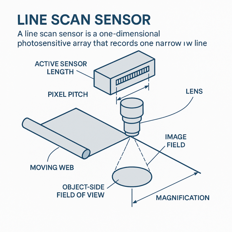
Line Scan Sensor Basics: Pixel Count, Pitch, and Lens Coverage
10 min read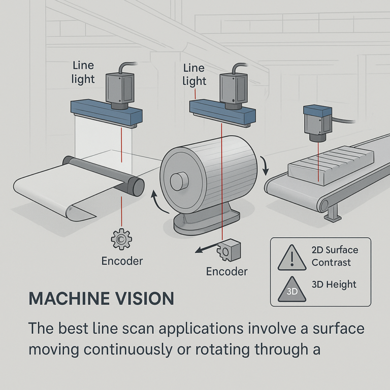
Line Scan Applications: Web Inspection, Cylinders, and 2D Limits
11 min read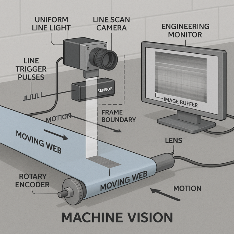
How Line Scan Imaging Works: Motion, Encoders, and Image Capture
11 min readAbout SUPERIOR OPTICS
SUPERIOR OPTICS specializes in CCTV lenses, machine vision optics, and custom optical solutions for security, industrial imaging, and specialty applications. We also provide professional lens selection and application support.