

How to Balance Aperture, Depth of Field, and Diffraction in Vision
A practical method for selecting an aperture range that covers part-height variation without sacrificing feature contrast, exposure margin, or production speed.
Key Takeaways
The defensible Depth of Field decision is an approved aperture range—not the smallest available opening—supported by feature, exposure, motion, and field-performance tests.
- Convert object-height variation into nearest, nominal, and farthest inspection planes before selecting an f-number.
- Set image-space blur tolerance from required feature contrast and algorithm performance rather than adopting an arbitrary pixel count.
- Use the widest aperture that covers the required depth range so exposure time and illumination demand remain manageable.
- Compare estimated diffraction blur with pixel pitch and feature scale, then verify the result using production-representative targets.
- Document an approved aperture range and reject adjustments that compromise edge performance, motion margin, or lighting stability.
The Short Answer
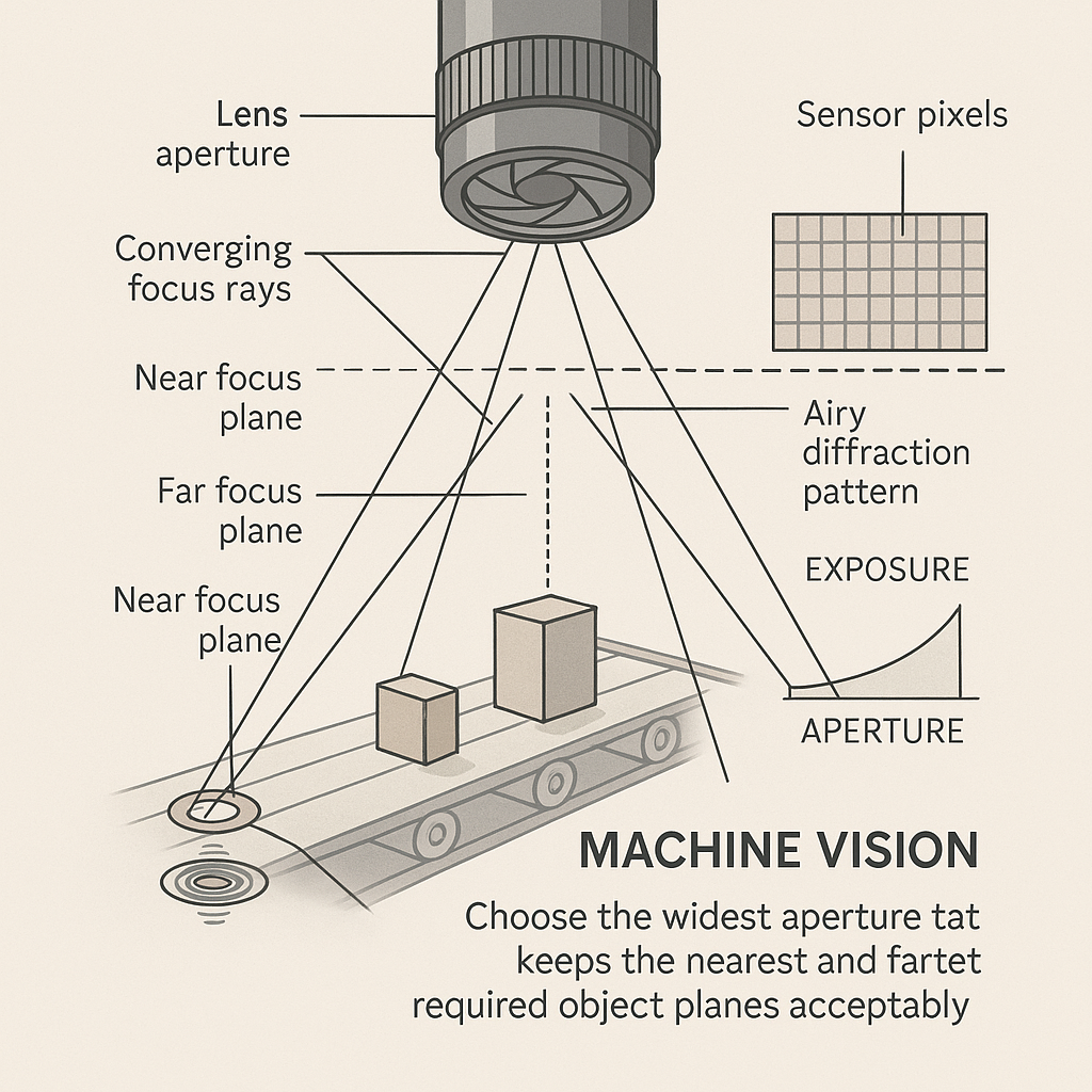
Choose the widest aperture that keeps the nearest and farthest required object planes acceptably sharp at production speed. Then estimate diffraction blur, compare it with pixel pitch and the feature contrast required by the inspection, and test the candidate settings across the full image field. Stopping down increases Depth of Field but reduces collected light and increases diffraction, so the answer is usually a validated f-number range rather than one theoretically perfect setting. If no range satisfies focus, exposure, and resolution together, change the lighting, magnification, sensor, working distance, or lens architecture.
The optimal f-number is the aperture range that supplies enough focus tolerance and exposure while keeping diffraction below the inspection’s usable resolution threshold. That aperture and diffraction trade-off must be tied to a real defect, edge, code, or measurement—not merely to whether an image looks sharp on a monitor.
The Aperture Trade-Off in Machine Vision
Depth of Field is the object-distance interval within which defocus blur remains below a selected circle-of-confusion limit. A higher f-number means a smaller aperture: focus tolerance grows, but less light reaches the sensor and diffraction increases. A lower f-number admits more light and supports shorter exposures, but reduces focus tolerance. These relationships are documented in the machine-vision aperture overview from 1stVision.
Machine Vision Aperture Trade-Off Table: What Changes When You Open or Stop Down the Lens
| Aperture direction | Depth range | Exposure and illumination demand | Motion-blur control | Diffraction risk | Resolution and contrast implication | Best-fit inspection condition |
|---|---|---|---|---|---|---|
| Open aperture / low f-number | Narrower | More light; lower demand | Supports shorter exposure | Lower | Aberrations or defocus may dominate | Flat target, limited light, or fast motion |
| Mid-range / balanced f-number | Moderate | Moderate | Usually retains exposure margin | Increasing | Often the most useful compromise, subject to lens data and testing | General inspection with controlled height variation |
| Stopped down / high f-number | Wider | Less light; higher demand | Longer exposure may increase motion risk | Higher | Better defocus tolerance but lower fine-detail contrast can result | Static or well-lit targets with meaningful height variation |
| Beyond the practical diffraction limit | Wider geometrically | Highest demand | Least exposure margin | High | Added depth no longer compensates for lost task contrast | Avoid unless coarse features remain reliably detectable |
A full stop reduction in aperture halves the admitted light, according to the cited machine-vision source. Whether that matters depends on available illumination, sensor response, line speed, and the exposure ceiling imposed by motion.
Define Inspection Requirements Before Choosing an F-Number
Calculate the required depth range from object-height variation
Record the nearest and farthest acceptable object surfaces relative to the lens, including fixture tolerance, part warp, conveyor runout, and changeover error. Focus calculations describe geometric limits; they don’t prove that an algorithm can detect a low-contrast defect at those limits.
Set the nominal focus plane deliberately. Centering it between the near and far surfaces is a useful starting inference, not a universal rule, because near and far focus tolerance need not be operationally equivalent.
Set the smallest feature and acceptable image-space blur
Translate the smallest required feature into sensor pixels at the selected magnification. Then decide how much contrast loss the detector, code reader, or metrology routine can tolerate. One-, two-, or four-pixel blur allowances can be trial criteria, but none is a universal pass threshold, as the Commonlands machine-vision focus guidance explains.
Account for magnification, sensor, and working distance
Magnification determines how object-space detail maps to the sensor. Pixel pitch affects sampling, while sensor format and working distance constrain focal length and field coverage. Resolve those variables before aperture; the workflow for machine vision lens selection by field of view, sensor, and working distance covers that earlier decision.
Include conveyor speed and allowable motion blur
Set an exposure ceiling from the distance a feature may move during capture. Faster motion requires shorter exposure or controlled strobed illumination. If stopping down forces exposure beyond that ceiling, the extra focus tolerance has not improved the inspection—it has exchanged defocus risk for motion blur.
How to Balance Aperture and Depth of Field Step by Step
- Start with the widest practical aperture. Establish a setting that meets exposure and motion requirements without saturation. Wide-open performance may be limited by lens aberrations, so treat it as the starting boundary rather than the presumed answer.
- Stop down only until the required Depth of Field is covered. Test the nearest, nominal, and farthest object positions. Don’t add unused focus tolerance at the expense of light and contrast.
- Check the diffraction budget. Estimate the Airy-disk diameter and compare it with pixel pitch, sampled feature width, and required contrast. Reject a setting when diffraction consumes the task’s resolution margin.
- Recheck illumination at production speed. Include source variation, controller limits, exposure time, gain, and thermal constraints. Avoid validating with a brighter bench setup than the production station can sustain.
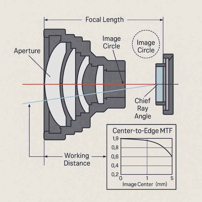
- Validate center-to-edge performance. Use representative parts at field center, corners, and any algorithm-critical region. Real-lens aberrations can reduce sharpness even where a geometric depth calculation predicts acceptable focus.
The output should be a bounded setting such as “approved from f/5.6 through f/8 under the specified lighting and line speed,” not “use f/8.” The example is a documentation format, not a recommendation for every system.
Identify the Diffraction-Limited Aperture for Your Inspection Task
Relate diffraction blur to pixel size and feature contrast
For a circular aperture, Airy-disk diameter can be estimated as:
d ≈ 2.44 × λ × N
where d is image-plane diameter, λ is wavelength, and N is f-number. At 550 nm, the estimated diameters are about 5.4 µm at f/4, 10.7 µm at f/8, and 14.8 µm at f/11. These are screening calculations from the verified formula, not automatic pass/fail limits.
A 10.7 µm disk spans more than two 5 µm pixels, but that fact alone doesn’t disqualify f/8. Pixel integration, lens aberrations, sampling, feature size, illumination spectrum, and the algorithm’s contrast requirement all affect the result.
Why smaller pixels narrow the usable range
As pixels get smaller, diffraction blur covers more pixels at the same wavelength and f-number. The diffraction-limited aperture may therefore arrive earlier in pixel terms, even though smaller pixels provide denser sampling. Compare complete-system contrast at the required spatial frequency rather than equating pixel count with resolved detail.
Separate sampling, lens, and diffraction limits
- Sampling: the sensor lacks enough samples across the feature.
- Lens performance: aberrations or field variation reduce contrast.
- Diffraction: stopping down spreads point energy over a larger area.
The practical limit is their combined effect. Lens MTF data at relevant apertures and field positions can narrow the candidates, but representative-image testing remains necessary.
When diffraction can be acceptable
A setting beyond a pixel-based rule of thumb may still pass when the inspection uses large, high-contrast features. Conversely, a nominally acceptable Airy diameter may fail on faint scratches or precision edges. The decision boundary is feature detectability and measurement repeatability, not an isolated optical number.
Choose the Optimal F-Number for Machine Vision by Constraint
| Dominant constraint | Aperture bias | Required verification |
|---|---|---|
| Object-height variation | Stop down cautiously | Near/far feature contrast and edge performance |
| Fast motion | Open aperture or add efficient strobed light | Motion displacement, exposure margin, saturation |
| Illumination or thermal limit | Favor a wider aperture | Lens aberrations and focus tolerance |
| Fine features or metrology | Avoid excessive stopping down | MTF, edge repeatability, distortion, field uniformity |
The optimal f-number for machine vision is therefore application-specific. If the candidate ranges for focus, motion, lighting, and contrast do not overlap, aperture adjustment alone cannot close the specification.
Lens, Camera, and Lighting Choices That Expand the Range
A suitable lens needs the required sensor coverage, resolution at the working distance, usable aperture control, and acceptable field performance. Compare available Machine Vision Lenses against those requirements rather than buying by focal length and mount alone.
When dimensional stability is the governing requirement, evaluate telecentric or low-distortion optics and verify their measurement behavior over the specified depth range. Before selecting a smaller aperture, improve illumination geometry, coupling efficiency, source placement, or strobe timing where feasible. More efficient delivery may preserve both exposure time and focus tolerance without excessive thermal load.
Changing magnification, working distance, or pixel pitch can create a usable aperture overlap when the original architecture cannot. For short-wave infrared designs, wavelength changes the diffraction estimate; use a wavelength-specific process such as SWIR lens selection for InGaAs inspection systems.
If no standard product meets the combined sensor, wavelength, envelope, focus, and resolution limits, assess optical lens assemblies for OEM vision systems rather than forcing the requirement onto an unsuitable catalog lens.
Common Aperture Selection Mistakes
- Stopping down to the minimum opening: geometric focus tolerance rises, but diffraction and illumination demand may erase useful contrast.
- Opening solely for brightness: exposure improves while part-height variation may move required surfaces outside acceptable focus.
- Trusting the aperture-ring marking at close focus: request manufacturer data or test the configured lens instead of assuming the nominal marking fully describes system behavior.
- Testing only at image center: corner performance may govern a code, measurement edge, or defect zone.
- Approving optics at reduced line speed: later speed increases can invalidate exposure and motion margins.
- Using a monitor as the acceptance tool: pass the production algorithm and repeatability criteria, not a subjective sharpness review.
Validate the Selected Aperture Under Production Conditions
Build a test matrix covering candidate f-numbers, nearest/nominal/farthest positions, relevant field locations, production line speed, and expected lighting variation. Measure feature contrast, detection rate, code readability, or dimensional repeatability using the actual acceptance criterion. Calculated near and far limits are only starting points; depth-of-field and circle-of-confusion fundamentals show that the result depends on the chosen blur criterion.
Record the lens identifier, focus lock, aperture setting, working distance, illumination settings, exposure, gain, wavelength, line speed, and approved adjustment limits. This turns aperture from an installer preference into a controlled system parameter.
For an aperture-range and lens-suitability review, submit the sensor format and pixel pitch, field of view, working distance, feature size, object-height variation, wavelength, and maximum line speed. Those inputs allow the focus, diffraction, exposure, and lens constraints to be reviewed together.
Frequently Asked Questions
What f-number gives the best compromise between Depth of Field and diffraction?
No universal f-number does. Start with the widest setting that meets exposure and motion limits, then stop down until the required near-to-far range passes. Compare diffraction estimates with pixel pitch and feature scale, and validate contrast across the field. The approved result should usually be a range, not one nominal number.
Does increasing the f-number always improve Depth of Field in a machine vision system?
Increasing the f-number increases geometric focus tolerance, but it does not always improve inspection performance. Less light may require longer exposure or higher gain, while diffraction can reduce fine-detail contrast. Judge improvement by feature detection, code reading, or measurement repeatability at the required object positions and production speed.
How can I determine whether diffraction blur is too large for my camera pixel size?
Estimate Airy-disk diameter with d ≈ 2.44λN, using the inspection wavelength and f-number. Compare the result with pixel pitch and the image width of the smallest required feature. Treat that comparison as screening only; confirm acceptability by measuring task contrast and algorithm performance on representative targets.
Should I add more illumination or use a wider aperture for a fast-moving part?
Use the option that preserves both exposure time and required focus tolerance. A wider aperture collects more light but may blur surfaces displaced from the focus plane. Efficient strobed illumination can support short exposure without reducing focus range, provided peak power, thermal limits, uniformity, and saturation remain within specification.
How does magnification affect the usable aperture range in close-up inspection?
Higher magnification maps smaller object details onto more sensor area but generally makes object-side focus tolerance more restrictive. It can also change working distance, field coverage, and lens performance. Recalculate the near and far requirements after changing magnification, then retest diffraction, exposure, and edge contrast rather than retaining the previous aperture.
Topics
Related Articles
Lens Specifications Explained: Focal Length, F-Number, and MTF
12 min read
Custom Lens RFQ Checklist: Requirements OEM Buyers Must Define
10 min read
Choosing the Right Surveillance Camera Lens for Optimal Security Coverage
11 min readAbout SUPERIOR OPTICS
SUPERIOR OPTICS specializes in CCTV lenses, machine vision optics, and custom optical solutions for security, industrial imaging, and specialty applications. We also provide professional lens selection and application support.