


M12 vs C-Mount and CS-Mount: Choosing Interfaces and Lens Adapters
A buyer-focused comparison of M12, C-mount and CS-mount interfaces, including flange geometry, sensor coverage, focus travel and adapter validation.
Key Takeaways
The M12 vs C-Mount and CS-Mount decision starts with camera geometry and optical requirements, not the thread name alone.
- Use M12 where compact packaging outweighs the serviceability and adjustment options commonly available with larger lens families.
- Treat C-mount and CS-mount as mechanically similar but axially different interfaces: their shared thread does not make their focus positions interchangeable.
- Validate image circle, corner quality, distortion and sensor compatibility independently of mechanical attachment.
- A CS-to-M12 adapter changes the connection geometry but cannot guarantee focus reach, alignment, clearance or image performance.
- Approve production fit only after testing the actual camera, holder, adapter and lens with documented assembly settings.
The Short Answer
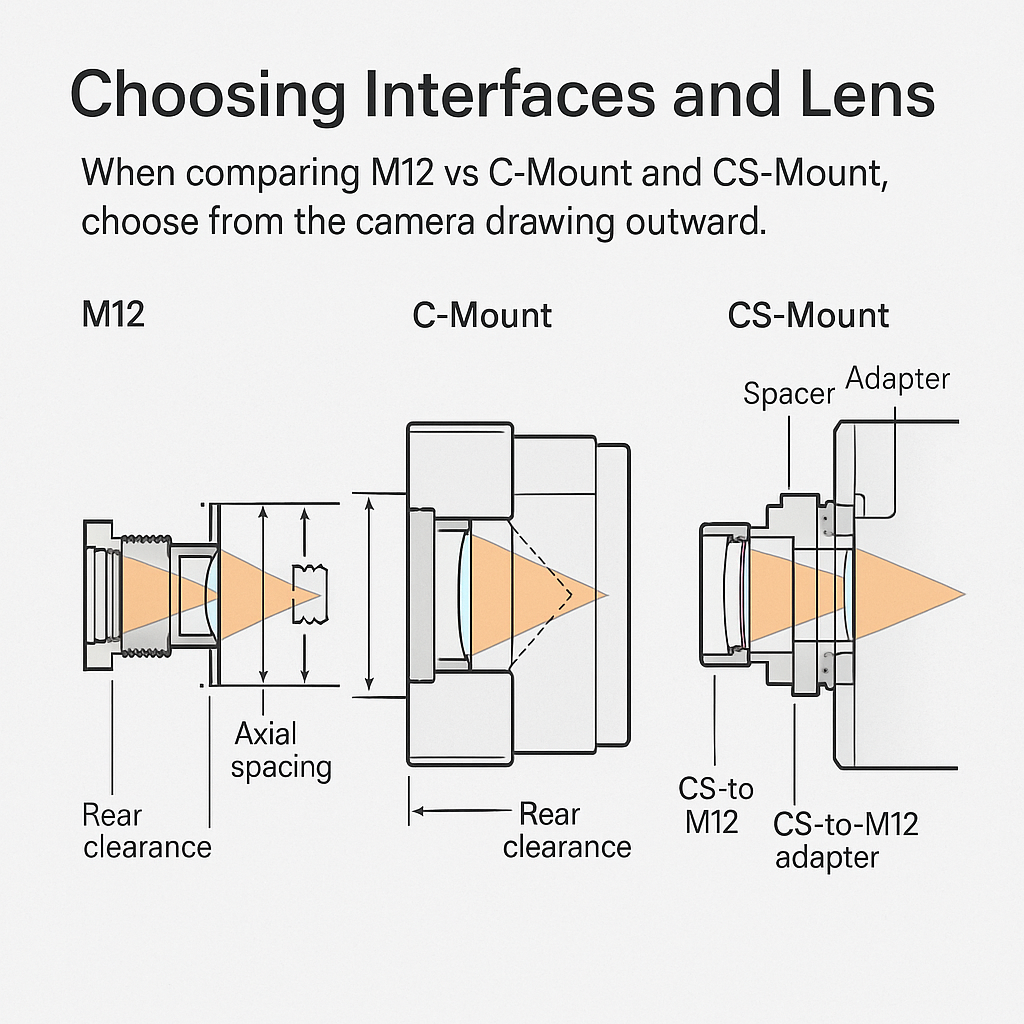
When comparing M12 vs C-Mount and CS-Mount, choose from the camera drawing outward. M12 generally suits compact board-level assemblies; C-mount provides a larger established interface with a 17.526 mm flange focal distance; CS-mount uses the same 1-inch, 32-TPI thread as C-mount but a 12.526 mm distance. An adapter can connect unlike interfaces, yet it does not prove focus reach, sensor coverage, alignment or clearance. Validate the complete axial stack, holder adjustment, rear protrusion, image circle and locking method on the intended camera.
M12 vs C-Mount and CS-Mount: The Interface Selection Decision
Choose M12 when the lens must fit close to a board-level camera and the holder can provide adequate focus adjustment and retention. Choose C-mount when the camera is designed around its larger threaded interface and 17.526 mm flange focal distance. Choose CS-mount when the camera and intended lens family use the shorter 12.526 mm distance.
Those C- and CS-mount dimensions are established interface facts, not nominal packaging estimates. The two mounts share a 1-inch, 32-TPI thread, according to The Imaging Source’s mount comparison, but the 5 mm difference in flange focal distance changes where the lens must sit.
M12 vs C-Mount vs CS-Mount: Mechanical Interface and Integration Comparison
| Selection factor | M12 lens mount | C-mount | CS-mount | Buyer validation |
|---|---|---|---|---|
| Packaging priority | Compact board-level assembly | Larger established interface | C/CS thread with shorter axial distance | Housing envelope and service access |
| Common thread | M12 × 0.5 mm | 1-inch, 32 TPI | 1-inch, 32 TPI | Actual drawing and thread engagement |
| Flange dependency | Holder- and camera-dependent | 17.526 mm | 12.526 mm | Datum, tolerance stack and focus reach |
| Focus adjustment | Often by threading the barrel | Lens or camera arrangement | Lens or camera arrangement | Usable travel after locking |
| Rear clearance | Lens and holder specific | Camera specific | Shorter mount distance increases sensitivity | Sensor cover, filter and housing clearance |
| Sensor fit | Lens-specific image circle | Lens-family dependent | Lens-family dependent | Active sensor area and corner test |
| Adapter use | Requires complete stack validation | C lens can fit CS with 5 mm spacing | Host for C lens or an M12 adapter | Alignment, light sealing and retention |
Decision summary: compact embedded assemblies often favor M12; accessible industrial systems may benefit from C-mount; CS-mount is appropriate when the camera’s shorter flange geometry and lens family are intentional. Adapter-based retrofits require a separate mechanical and optical qualification.
Compare the Mechanical Interfaces Before Selecting Optics
M12 packaging is compact but holder dependent
M12, also called S-mount, commonly uses an M12 × 0.5 mm thread. In a board-camera arrangement, the lens threads into a holder attached at or near the sensor PCB. Turning the fine thread can provide focus adjustment, so holder height, thread depth and locking method become part of the optical stack. Sunex’s mounting-format guidance also cautions that not every board-mount lens is M12.
That compact arrangement can reduce packaging volume, but the designation alone says nothing about barrel diameter, rear protrusion or tool access. Buyers evaluating M12 CCTV lenses still need the lens and holder drawings.
Why C-mount and CS-mount are not interchangeable by thread alone
A C-mount lens can be installed on a CS-mount camera with the required 5 mm spacer or extension ring. Without that spacing, correct focus at longer object distances may not be available. The reverse combination is normally impractical: a CS lens on a C-mount camera would need to sit farther inside the housing to reach its intended position.
This is the central C-mount vs CS-mount distinction. Thread engagement answers whether parts screw together; flange geometry answers whether the optical system can focus.
Locking, vibration and installation access
An adjustable interface also needs a repeatable retention method. Lock rings, set screws or approved locking compounds can affect barrel position and assembly access. Engineering inference: where vibration or repeated servicing is expected, procurement should request an allowed focus shift or image-based acceptance limit rather than accepting “locked” as a complete requirement.
How Sensor Format and Optical Requirements Affect Mount Choice
M12 lens sensor coverage must be checked against the active imaging area, not inferred from the mount size. A lens may attach and focus while producing dark corners or inadequate off-axis detail. Conversely, an image circle that covers the sensor does not establish sufficient resolution, acceptable distortion or compatible chief-ray behavior.
Use the actual sensor part number and operating mode. Cropped, binned or windowed modes may use a different active area from the sensor’s full dimensions. Review M12 lens sensor coverage and camera-sensor matching when translating pixel pitch, resolution and chief ray angle requirements into an optical specification.
Field of view must also be evaluated at the intended working distance. Changing the mount does not preserve framing automatically; focal length, sensor dimensions and object distance still control the result. Aperture requirements matter as well. Many M12 products use fixed apertures, while adjustable iris options are common in C- and CS-mount families, although the specific lens data sheet governs.
Focus travel can be consumed by the holder height, adapter shoulder, sensor cover glass or an added filter. Engineering implication: model the complete axial stack before ordering samples, then verify it physically because drawing tolerances can accumulate in either direction.
What a CS-to-M12 Adapter Changes—and What It Does Not
A CS-to-M12 adapter changes the mechanical interface presented by the camera. Depending on its design, it may provide an M12 female thread, establish a shoulder and position the lens within the CS-side envelope.
It does not certify that the M12 lens’s focal plane will coincide with the sensor. Nor does it establish image-circle coverage, resolution, distortion, chief ray angle, spectral response or acceptable corners. Those remain properties of the lens-camera combination.
Adapter-related failure modes can include insufficient thread engagement, a hard stop before focus, excessive rear protrusion, housing interference, tilt, decentering and stray-light paths. These are integration risks rather than evidence that the lens design itself is defective. For a deeper mechanical review, see M12 lens mechanical fit, including back focal length, threads, and clearance.
Adapter Validation Checklist for Camera and Holder Drawings
Use controlled drawings rather than catalog labels. Datums should make clear where the camera-side mounting surface, adapter shoulder, holder thread and sensor plane are measured.
| Validation item | Required input | What to inspect | Failure to rule out | Acceptance record |
|---|---|---|---|---|
| Camera-side geometry | Camera drawing | Thread, datum and shoulder | Incorrect seating | Drawing revision |
| Adapter geometry | Adapter drawing/sample | Both interfaces and axial length | Bottoming or loose fit | Part number and lot |
| M12 engagement | Lens and holder drawings | Usable turns through focus range | Strip risk or inadequate retention | Engagement at final focus |
| Axial stack | All component drawings | Nominal and tolerance limits | Focus outside travel | Focus position |
| Rear protrusion | Lens envelope | Clearance to filter and sensor area | Contact or blocked travel | Minimum clearance |
| Barrel clearance | Housing CAD/drawing | Diameter and tool access | Housing interference | Keep-out approval |
| Alignment | Assembled sample | Centering, tilt and retention | Uneven corner performance | Image and fit record |
| Optical coverage | Actual camera | Corners, shading and vignetting | Image-circle shortfall | Saved test images |
| Light sealing | Dark and illuminated tests | Gaps and internal reflections | Light leak or flare | Test condition/results |
| Repeatability | Multiple assemblies | Focus and image variation | Operator-dependent build | Assembly procedure |
A short stack-up example shows why nominal attachment is insufficient. C-mount and CS-mount differ by 5 mm, so a C lens on a CS camera needs that added spacing. If another adapter is introduced, its shoulder position and tolerance become additional terms; they cannot be ignored because the thread still engages.
Common Integration Scenarios
Compact CCTV and embedded cameras
M12 is usually the first interface to assess when board space and enclosure diameter dominate. Check whether focus can be reached without the rear lens structure approaching the filter or sensor package, and whether production staff can lock the barrel after adjustment.
Machine vision with service access
C-mount can be preferable when the camera already supports it and operators need access to focus or iris controls. That is a system-level selection, not proof that every C-mount lens meets the required sensor format or working distance.
Cross-supplier and custom assemblies
Treat M12 vs C-Mount and CS-Mount comparisons as controlled interface evaluations. For a custom assembly, mount geometry should be an explicit design input alongside field of view, spectral band, aperture, environment and acceptable corner performance.
Evaluate Cross-Supplier Samples Without Blaming the Wrong Component
Use the same camera, sensor mode, target, illumination, working distance and image-processing settings for each candidate. Record the holder, adapter and lens part numbers, plus the final axial position and locking condition. If day/night or non-visible operation is required, qualify suitable infrared camera lenses at the intended wavelengths rather than extrapolating from visible-light images.
Separate observations into two records:
- Mechanical fit: attachment, focus reach, clearance, thread engagement, retention and assembly access.
- Optical result: center and corner detail, field of view, distortion, shading, flare and spectral focus behavior.
This separation prevents an adapter-induced tilt or focus limit from being reported as poor lens resolution. Before approving an alternate source, document the tolerances and assembly controls that matter in production—not just the best sample’s focus setting.
Specify the Lens Mount Interface in an OEM RFQ
An actionable RFQ identifies the camera model, sensor part number, active mode, mount drawing and relevant housing keep-outs. Include the required field of view, object distance, wavelength range, aperture behavior, environmental conditions and any focus or iris adjustment expectations.
Attach dimensioned drawings for the camera face, holder, adapter and enclosure. State optical acceptance criteria separately from mechanical acceptance, and define how samples will be installed and locked. The machine vision lens RFQ checklist provides a structured starting point for supplier evaluation.
For an interface review, submit the actual camera, sensor, holder, housing and adapter drawings with working distance, field of view, wavelength and environmental requirements. SUPERIOR can then review fit assumptions, relevant lens options and the sample-validation plan without treating the mount label as proof of compatibility.
Frequently Asked Questions
Can a C-mount lens be used on a CS-mount camera?
Yes. A C-mount lens and CS-mount camera share the 1-inch, 32-TPI thread, but the lens requires 5 mm of added spacing because their flange focal distances differ. Use the correct spacer or extension ring, then verify focus reach, rear clearance, image coverage and retention on the assembled camera.
Can a CS-mount lens be used on a C-mount camera?
Generally, no. A CS-mount lens is designed for a 12.526 mm flange focal distance, while a C-mount camera places the mounting reference at 17.526 mm. Correct focus would require the CS lens to sit farther inside the camera, which is normally impractical and may create interference.
Does a CS-to-M12 adapter make any M12 lens compatible with a CS camera?
No. The adapter can provide the required thread connection and reposition the lens mechanically, but compatibility still depends on focus travel, thread engagement, rear clearance, alignment and sensor coverage. Resolution, distortion, chief ray angle and spectral behavior must also be evaluated on the actual camera.
How do I check whether an M12 lens covers my camera sensor?
Compare the lens’s specified image circle with the active sensor dimensions, then test the intended sensor mode on the actual camera. Inspect all corners for vignetting, shading and usable detail. Coverage alone is insufficient; confirm resolution, distortion and chief ray angle compatibility for the application.
What drawings should I provide when requesting a lens adapter or custom optical assembly?
Provide dimensioned camera-face, sensor-position, holder, adapter and housing drawings with identified datums and tolerances. Include thread details, shoulders, rear keep-outs, filter or cover-glass geometry and available adjustment travel. Add working distance, field of view, wavelength, aperture, environment and the intended focus-locking method.
Topics
Related Articles
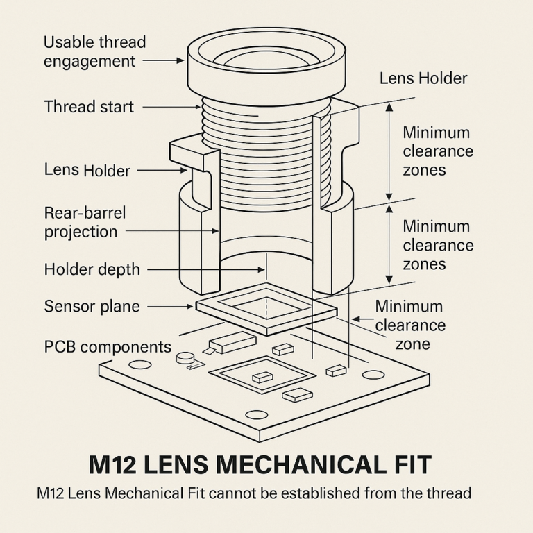
M12 Lens Mechanical Fit: Back Focal Length, Threads, and Clearance
10 min read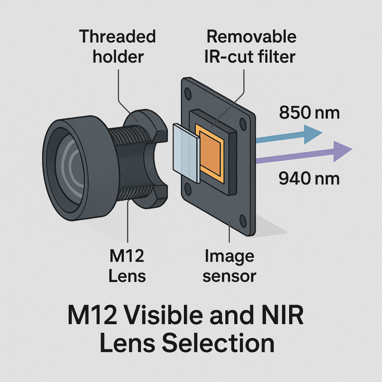
M12 Visible and NIR Lens Selection: Wavelengths and Filter Choices
11 min read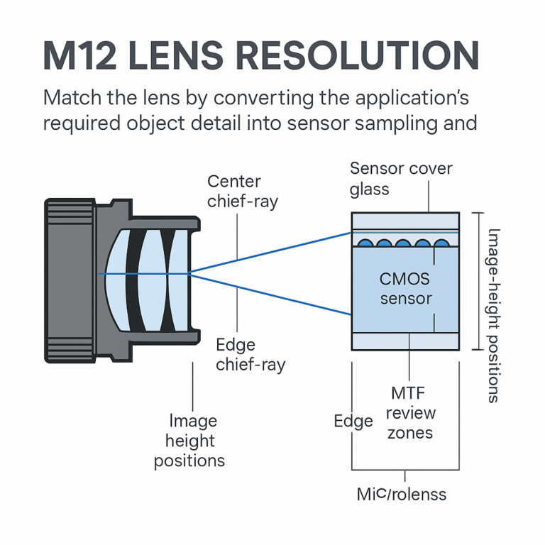
M12 Lens Resolution and CRA: Matching Optics to the Camera Sensor
11 min readAbout SUPERIOR OPTICS
SUPERIOR OPTICS specializes in CCTV lenses, machine vision optics, and custom optical solutions for security, industrial imaging, and specialty applications. We also provide professional lens selection and application support.