


M12 Camera MTF Testing: Chart Quality, RAW Images, and Repeatability
A buyer-focused protocol for separating lens performance from chart limits, focus error, module alignment and image-processing effects.
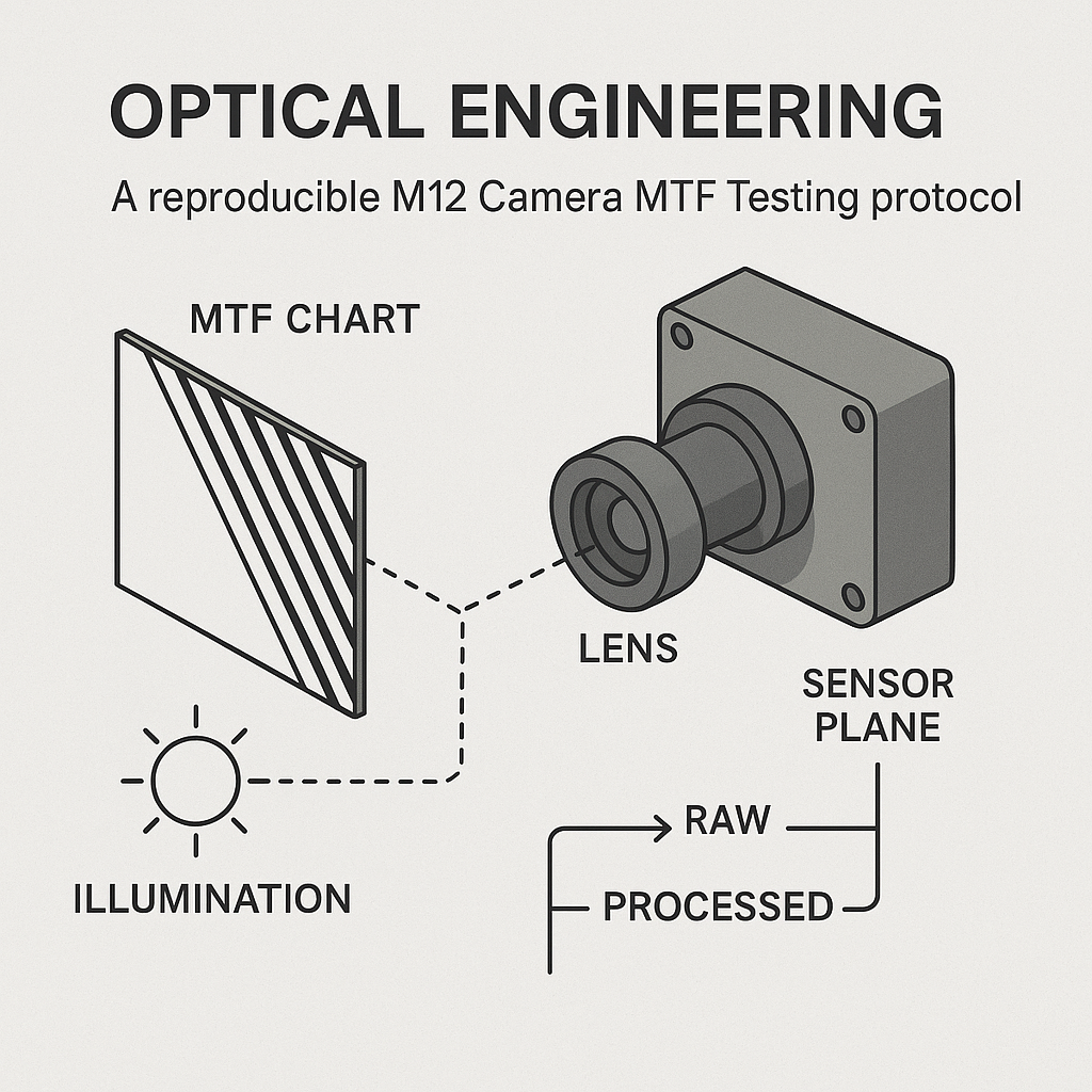
Key Takeaways
M12 Camera MTF Testing supports a defensible buying decision only when the chart, camera module, field positions, focus method and image pipeline are treated as one documented test configuration.
- Do not rank lenses from camera-level results produced with different sensors, focus rules, spectra, output pipelines or analysis methods.
- Qualify the chart at the intended geometry and sensor sampling conditions before blaming weak high-frequency response on the lens.
- Record RAW and processed outputs as separate configurations because demosaicing, sharpening, scaling and compression can change the reported response.
- Repeat captures, refocuses and remounts separately so setup variation is not mistaken for lens-to-lens variation.
- Escalate ambiguous results to controlled reruns or lens-only measurement rather than rejecting a supplier from one camera-level ranking.
The Short Answer
A reproducible M12 Camera MTF Testing protocol starts by defining the camera module, lens sample, field positions and decision purpose. The test team then qualifies the chart, fixes geometry and illumination, documents mounting and focus, and captures repeated images with locked settings. RAW data must be analyzed separately from processed output because the image pipeline can alter spatial-frequency response. Supplier samples should be ranked only when the chart, sensor mode, focus rule, output configuration and analysis metric are equivalent. Refocus and remount checks help determine whether a weak result belongs to the lens or the setup.
A camera-level MTF result is not a universal grade for an M12 lens. It is evidence about a particular lens, module, setup and output path. That distinction matters when an OEM is qualifying a second source or investigating a corner-performance shortfall.
What M12 Camera MTF Testing Measures at the Camera Level
Why lens-only and camera-level MTF are not interchangeable
A lens bench is intended to isolate optical component behavior. A chart-based camera measurement captures combined system response. SUPERIOR’s guide to M12 lens MTF reports identifies the lens, sensor, cover glass, focus, alignment and recorded-image processing as contributors to assembled-camera results.
Consequently, a lower camera-level value does not by itself prove that the lens is defective. The sensor sampling, chart projection, module tilt or processing path may be limiting the result. Conversely, aggressive edge enhancement can make processed response look stronger without demonstrating better bare-lens MTF.
When camera-level evidence is appropriate
Camera results are useful when the acceptance question concerns the delivered imaging system: for example, whether a module resolves application-relevant detail at the center and used corners. Lens-only measurement is more appropriate when the buyer must isolate lens manufacture from module assembly or sensor behavior.
Comparisons require matching aperture, focus distance, spectrum, spatial frequency, field position and measurement method. If any of these differ, the result should be presented as a separate configuration rather than a supplier ranking.
How Do You Test MTF on an M12 Camera?
Use this seven-step protocol:
- Set the decision purpose. Identify the camera module, lens serial or sample ID, sensor mode, working distance, spectrum, field points and acceptance metric.
- Qualify the chart. Verify that the projected target can support the frequencies being assessed at the chosen camera-to-chart geometry.
- Fix the setup. Record chart distance, camera orientation, illumination, exposure, gain and any reflection-control measures.
- Control mounting and focus. Document thread engagement, locking method, focus search range and the rule used to select best focus.
- Capture repeats. Keep settings fixed while acquiring multiple files, then conduct separate refocus and remount runs.
- Separate output paths. Analyze RAW and processed captures as different configurations, with pipeline settings and software versions recorded.
- Report boundaries. State field positions, metric, analysis method and rerun criteria; compare suppliers only under equivalent conditions.
This protocol is an engineering-control recommendation derived from the documented factors that affect camera-level results. It is not a claim that one universal fixture or repeat count fits every sensor and application.
Camera MTF Test Chart Qualification Checklist
A chart becomes part of the measurement system. Imatest’s chart-suitability documentation states that chart-based camera measurements include chart effects and that projected chart MTF must be high enough to support reliable camera measurement. Suitability depends on factors including chart data, field of view and sensor pixel count.
| Qualification item | What to verify | Why it affects the result | Record to retain |
|---|---|---|---|
| Target capability | Projected feature response at the frequencies of interest | An inadequate target can cap measured response | Chart type, size and suitability assessment |
| Condition and flatness | Clean surface, no visible damage, controlled mounting | Local defects or shape changes can create field-dependent error | Inspection record and setup image |
| Geometry | Distance, framing, chart orientation and camera pose | Projection onto the sensor changes with geometry | Dimensions and fixture references |
| Illumination | Coverage, stability and intended spectrum | Exposure or spectral changes create a different configuration | Source, warm-up practice and exposure data |
| Reflection control | Glare or flare visible around target regions | Unwanted light can reduce target contrast | Reference frame and shielding notes |
| Field coverage | Center, relevant mid-field and used corners are present | Center-only data cannot support edge acceptance | Region map |
| Baseline | Reference capture before sample comparisons | Helps reveal setup drift | Original image and analysis output |
For fisheye or strongly barrel-distorted systems, standard chart-suitability calculations may need modification. A chart that works for one module geometry should not automatically be approved for another.
Alignment and Focus Controls for M12 Lens MTF Measurement
Tilt, seating and mechanical stability
Camera-to-chart tilt can produce a field-dependent focus pattern that resembles lens decentering. A practical diagnostic is to inspect opposing field positions under the same focus setting. If the imbalance reverses after fixture changes or disappears after remounting, setup error remains a plausible explanation; this is an inference to investigate, not proof of the root cause.
Record whether the lens reached a mechanical stop, how many threads were engaged and how focus was locked. A loose barrel or inconsistent seating can make a nominally repeated test a different mechanical condition.
One focus rule for every sample
State whether focus is optimized at the center, at a weighted set of fields or at a fixed production position. Center-best focus can disadvantage a lens whose best system compromise occurs elsewhere. Changing the optimization rule between samples invalidates the ranking.
Measure center, application-relevant mid-field positions and the demanding used edge without moving the camera between regions. For systems where sensor coverage is a concern, review corner MTF performance together with image-circle and edge-quality constraints.
Spectral conditions also belong in the focus record. A module intended for an infrared lens application should be evaluated under the intended spectral use case rather than assumed to match visible-light focus behavior.
RAW Image MTF Analysis Versus Processed Image Results
RAW and processed files answer different questions. RAW image MTF analysis can reduce some pipeline ambiguity, but it still requires the sensor mode, channel treatment and analysis method to be known. Processed output evaluates the combined camera and pipeline that the application may actually use.
Demosaicing reconstructs color samples; noise reduction can suppress fine variation; sharpening can add edge overshoot; scaling changes sampling; and compression can alter edge structure. The verified SUPERIOR source notes that sharpening can produce camera spatial-frequency response above 1, which must not be described as bare-lens MTF.
Processed testing is valid when the buyer is approving delivered system output—provided every sample uses the same firmware, ISP profile and export path. The camera-module testing description from Commonlands likewise distinguishes lens-bench MTF from camera eSFR and reports capture settings with system-response curves.
RAW and Processed Configuration Documentation for Fair Comparisons
| Configuration item | RAW configuration record | Processed configuration record | Risk if undocumented |
|---|---|---|---|
| Sensor mode | Resolution, crop, bit depth and readout mode | Same, plus output resolution | Different sampling limits |
| Exposure controls | Exposure and gain; fixed or automatic status | Exposure, gain and white-balance status | Unequal noise or clipping |
| Demosaicing | Method used before analysis, if any | ISP or software method and version | Different edge reconstruction |
| Noise reduction | Off or documented analysis treatment | Strength and spatial/temporal modes | Fine detail may be suppressed |
| Sharpening | None, or explicitly documented | Strength, radius or profile where available | Artificial response boost |
| Scaling and crop | Any preprocessing dimensions | Resize, digital zoom and crop | Changed sampling and field mapping |
| File format | RAW packing and decoder | Format, quality and compression | Edge artifacts or information loss |
| Analysis | ROI, channel, metric and software version | The same details | Unlike metrics may be ranked together |
If a supplier provides only a plotted curve, request the configuration record and representative source files. A curve without sample identity, field coordinates and processing status has limited value for approval.
How to Demonstrate MTF Test Repeatability
MTF test repeatability should be decomposed rather than represented by one repeated screenshot. Each run below changes one source of variation while holding the others as stable as practical.
| Repeatability check | What changes | What remains controlled | Decision use |
|---|---|---|---|
| Repeat capture | File acquisition only | Lens, focus, fixture and settings | Detect capture or pipeline instability |
| Refocus | Focus search repeated | Mount, geometry and settings | Quantify focus-selection sensitivity |
| Lens remount | Lens is removed and reseated | Camera, chart and procedure | Expose mounting sensitivity |
| Setup rebuild | Camera or fixture is repositioned | Documented method and hardware | Test setup reproducibility |
| Multiple samples | Lens sample changes | Module and test configuration | Estimate sample-to-sample variation |
| Operator review | Analyst or operator changes | Files, instructions and metric | Detect procedural ambiguity |
No universal repeat count is supported by the supplied evidence. The buyer should set the count and rerun threshold from the acceptance risk, observed variation and cost of a false rejection. When two runs disagree enough to change pass/fail status, pause the ranking and investigate focus, mounting, chart condition, metadata and analysis regions.
Retain original files, metadata, sample identity, setup photographs, analysis outputs and software versions. Programs requiring stronger traceability can adapt record controls used in automotive optical component validation, while setting requirements appropriate to their own application.
Using M12 Camera MTF Results for Sample Approval Decisions
Equivalent configurations are the minimum basis for fair comparison. This principle should be built into the wider M12 sample approval workflow so a second-source candidate is not rejected because it was tested with a different focus rule or processing profile.
Before attributing a weak result to the lens, ask four questions:
- Was the chart qualified for this geometry and sensor sampling condition?
- Did repeated captures, refocuses and remounts agree closely enough for the decision?
- Were field positions, output path and metric identical?
- Does another check support the suspected failure mode?
MTF alone does not establish distortion, centering, relative illumination or mechanical fit. Those checks belong in a broader optical lens quality control plan. A lens may meet an MTF threshold yet fail the application through geometry or assembly incompatibility.
When camera data remain inconclusive, the defensible choices are a controlled rerun, a fixture investigation, additional samples or lens-only measurement. They cost more time than accepting one ranking, but they reduce the risk of rejecting a capable supplier—or approving a result created by processing rather than optics.
Request a Controlled M12 Lens Evaluation Plan
For a configuration-review discussion, provide the camera module, sensor format, target field of view, working distance, operating spectrum, required output type, current chart, camera settings and proposed acceptance criteria. These inputs allow the evaluation plan to separate application-level camera evidence from component-level lens evidence.
Frequently Asked Questions
Can two M12 lenses be compared if they were tested on different camera modules?
Not as a direct lens ranking. Different sensors, cover glass, alignment, focus and processing can change camera-level response. The results may describe each assembled system, but they do not isolate lens performance. Use one controlled module configuration or supplement the evidence with comparable lens-only measurements.
Should a buyer request RAW files when reviewing an M12 camera MTF result?
Yes, when RAW capture is available, but files alone are insufficient. Request the decoder or analysis method, sensor mode, exposure, gain, field coordinates and sample identity. Also retain processed files when delivered image quality is the acceptance target. RAW and processed evidence should remain separate configurations.
What test records should accompany M12 lens sample approval data?
The package should identify the lens sample and camera module, chart, geometry, illumination, spectrum, exposure, gain, focus rule, field positions, output type, processing settings, software version and reported metric. Original images, metadata, setup photographs and repeat-run results make disagreements easier to investigate.
Can sharpening make one M12 camera lens appear better than another?
Yes. Sharpening or edge enhancement can increase measured camera response and introduce edge overshoot; a verified SUPERIOR technical source notes that processed spatial-frequency response can exceed 1. Such output may represent application performance, but it must not be labeled as bare-lens MTF or compared with unsharpened data.
When should a camera-level MTF result be supplemented with lens-only testing?
Add lens-only testing when the decision requires optical-component isolation, camera results conflict after controlled reruns, or module alignment and processing cannot be held equivalent. It is also useful when diagnosing whether a field-performance problem comes from the lens itself or from sensor, cover-glass, focus or assembly conditions.
Topics
Related Articles
M12 Catalog vs Custom Lenses: Justifying Development for OEM Cameras
11 min read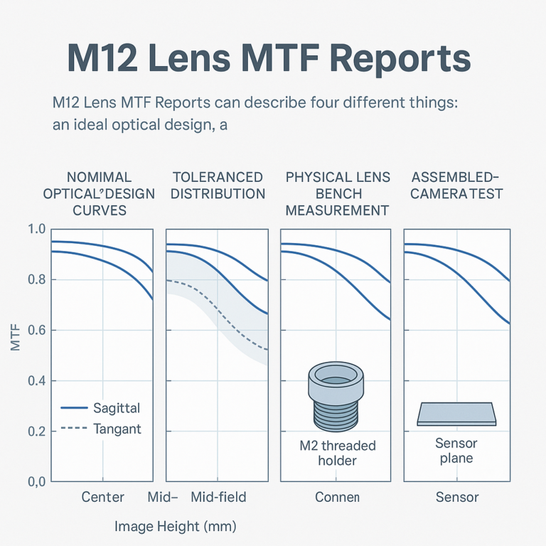
M12 Lens MTF Reports: Comparing Nominal, Toleranced, and Measured Data
10 min read
M12 Sample Approval and Second Sources: Comparing Equivalent Lenses
10 min readAbout SUPERIOR OPTICS
SUPERIOR OPTICS specializes in CCTV lenses, machine vision optics, and custom optical solutions for security, industrial imaging, and specialty applications. We also provide professional lens selection and application support.