


M12 Through-Focus Performance: Testing Distance and Aperture Limits
A practical method for validating an assembled M12 camera across required object distances, apertures, field positions and lighting conditions.
Key Takeaways
Through-Focus Performance should be accepted against the deployed camera’s required distances, field positions, lighting and task—not a lens’s single nominal focus claim.
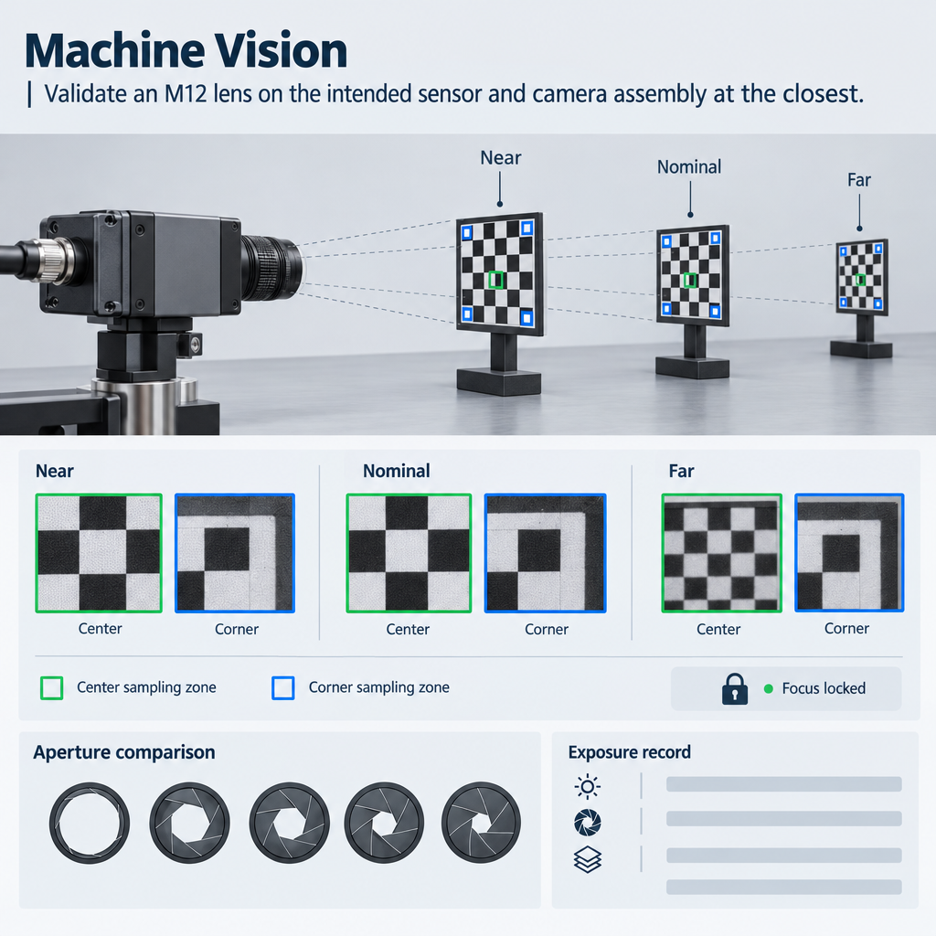
- Test the closest, nominal and farthest required object distances with the production focus setting locked.
- Run a separate refocused sequence to distinguish available focus travel from fixed-focus operating range.
- Judge center and required edge positions because center sharpness alone does not establish system acceptance.
- Record aperture, illumination, exposure and gain so apparent depth-of-field gains are not detached from their light cost.
- Convert accepted conditions, exclusions and retest rules into purchasing and production-control requirements.
The Short Answer
Validate an M12 lens on the intended sensor and camera assembly at the closest, nominal and farthest required object distances. First lock the production focus setting; then run a separate refocused sequence. At every distance, compare the center and required edge positions while holding illumination, processing and acceptance criteria constant. Repeat the sequence at each viable aperture, recording exposure and gain. Through-Focus Performance passes only where the application-critical feature remains detectable or measurable under the deployed operating limits—not merely where a target appears subjectively sharp.
A lens that resolves a chart at one convenient distance may still fail an inspection, recognition or surveillance task elsewhere in the specified range. The buyer therefore needs an operating envelope for the assembled camera, not an isolated statement that the lens can be focused at a particular distance.
What Through-Focus Performance Means for an M12 Lens
Performance across the required object-distance range
The test range starts with the application: nearest object, normal working position and farthest object. Intermediate points belong in the plan when feature size, field coverage or expected focus margin changes materially between the endpoints. Guidance on M12 lens working distance and usable depth of field also identifies sensor dimensions, pixel pitch, feature size, illumination and exposure limits as relevant specification inputs.
Working distance and minimum object distance aren’t interchangeable. The former is a stated housing-to-object gap; the latter is the closest specified distance under stated focus or performance conditions. The distance datum must therefore be recorded. Otherwise, two laboratories can place the same target at nominally identical but physically different positions.
Why one nominal focus distance is insufficient
A favorable center result doesn’t establish edge quality or the usable M12 lens focus range. As object distance changes, field curvature, astigmatism and spherical aberration can alter the balance between center and corner performance. The machine-vision distance guidance recommends checking aligned targets at the required near and far positions and comparing the center with opposite corners.
Focus adjustment versus application acceptance
For an M12 assembly, focus is normally adjusted by moving the lens in its threaded holder. A refocused image shows whether usable mechanical travel exists. It does not prove that one locked production position covers the whole range. Acceptance instead asks whether the required feature, edge location or algorithm output remains within its limit at the deployed setting.
Set the M12 Lens Testing Conditions Before Measuring Performance
Camera, sensor and lens configuration
Record the lens identifier and sample, holder, locking method, sensor model, active dimensions, pixel pitch, cover glass or filter stack, processing state and image orientation. Assembled-camera results include focus, sensor, filters, alignment and documented processing; they are not interchangeable with stand-alone lens data.
Distances, target details and acceptance criteria
List the distance datum and every required target position. At each point, define the smallest application-critical feature and where it may appear in the field. Possible acceptance measures include target-detail visibility, MTF, edge-localization error or inspection-algorithm performance. If MTF is used, measured M12 lens MTF data must be compared at matching aperture, focus distance, spectrum, spatial frequency, field position and method.
Illumination, exposure, gain and contrast
Document spectrum, target contrast, light geometry, exposure time, gain and permitted image processing. Lock these where the comparison requires it. If exposure must change to compensate for aperture, record the change and verify that it remains inside the application’s motion and noise constraints.
Aperture and focus-setting method
Identify the stated f-number or physical aperture configuration and whether it is fixed, interchangeable or adjustable. Record how best focus was selected, which field position controlled that choice, and how the lens was locked. Photographing or marking the final thread position can support repeatability, although it does not replace an image-quality check.
Run a Through-Focus Test Across Distance, Aperture and Field Position
Close, nominal and far conditions
A defensible Through-Focus Performance sequence begins with the production focus locked. Move the target or camera to each specified distance without touching focus. Keep target alignment and the defined distance reference consistent.
A second sequence may refocus at every distance. That sequence answers a different question: whether focus travel and clearance permit best focus at each object position. Usable M12 travel also depends on thread engagement and clearance to the sensor stack, so a mathematically reachable focus position may still be mechanically unsuitable.
Center and corner image quality by distance
Measure the center, relevant mid-field locations and the most demanding required edge or corner. Opposite-corner imbalance can indicate tilt or assembly alignment, while similar edge degradation around the field may point toward a lens-distance limitation. Those patterns are diagnostic indications, not proof; rotation or substitution tests may be needed.
Exposure changes at each aperture
Repeat the locked-focus and, where useful, refocused sequences for every candidate aperture. Preserve the raw exposure record. A smaller aperture that passes only through an exposure time incompatible with object motion is not an acceptable solution for that operating condition.
Compare Aperture Configurations Without Confusing Depth of Field and Resolution
Light collection, tolerance and detail
Stopping down generally increases geometric depth-of-field tolerance, but it reduces light throughput and can eventually increase diffraction blur. The practical choice is therefore the aperture that passes the task across the required range while remaining compatible with available light, exposure and gain—not simply the smallest opening.
The engineering balance is covered in more detail in aperture, depth of field and diffraction trade-offs. Aperture performance testing should still be repeated on the intended module because the sensor and processing affect the delivered image.
Edge improvement is conditional
Stopping down may improve an edge affected by aberration or focus variation, but the result must be checked at every required distance. If the center passes while a required corner fails, accepting the lens on center data alone transfers the risk into installation or production.
When a smaller aperture loses useful detail
The relevant failure is application-specific: unreadable markings, unstable edge coordinates or algorithm confidence below its approved threshold. Subjective sharpness is a weak substitute. Compare like-for-like captures, then verify the chosen aperture under the lowest permitted illumination or highest required speed.
Use the Through-Focus Results Table to Make an Acceptance Decision
Through-focus results should be assessed at required distances, apertures, field positions and lighting conditions—not inferred from one focus-distance specification. The following is a test-record template, not measured product data.
Through-Focus Results by Distance, Aperture, Field Position, Contrast, Exposure, and Application Acceptance
| Test distance | Focus condition | Aperture | Field position | Feature or contrast | Lighting | Exposure and gain | Observed image quality | Outcome | Notes or action |
|---|---|---|---|---|---|---|---|---|---|
| Closest required | Locked production focus | Candidate setting | Center and required edges | Defined critical feature | Stated production condition | Record actual values | Enter metric or task result | Pass, conditional or fail | Note edge/focus limit |
| Intermediate near | Locked production focus | Candidate setting | Same positions | Same feature/contrast | Same condition | Record | Enter result | Assign against threshold | Investigate transition |
| Nominal working | Locked production focus | Candidate setting | Same positions | Same criterion | Same condition | Record | Enter result | Assign | Baseline comparison |
| Intermediate far | Locked production focus | Candidate setting | Same positions | Same criterion | Same condition | Record | Enter result | Assign | Check field consistency |
| Farthest required | Locked production focus | Candidate setting | Same positions | Same criterion | Same condition | Record | Enter result | Assign | Define range endpoint |
| Stress condition | Locked, then refocused if planned | Selected setting | Worst required position | Critical low-contrast feature | Lowest light or highest speed | Record limits | Enter result | Assign separately | State exclusion or retest |
Mark a condition as passing only when the required feature is resolved or measured at the applicable field position and permitted exposure. “Conditional” can identify a result that passes only after refocusing, at restricted illumination or outside a required edge zone. It must not be merged into an unconditional fixed-focus pass.
Illustrative decision, not test data: suppose a camera passes its task at the near and nominal distances with focus locked but passes the far point only after refocusing. The evidence supports focus capability at the far point, not a fixed-focus range covering all three positions. The corrective choices are to narrow the claimed range, change aperture within lighting limits, or evaluate another optical configuration.
Diagnose Focus-Setting Problems Versus an Unsuitable Operating Range
Signs of an incorrect module focus
If all field positions improve together after a small focus adjustment, and the new locked position improves the required distance set without creating another failure, the initial focus setting is a plausible cause. Confirm it with repeated assembly and lock-down checks rather than one adjustment.
Strong asymmetry between opposite corners suggests checking target alignment, sensor-lens tilt or holder alignment. If rotation causes the weak region to rotate with the lens, lens-related variation becomes more plausible; if it remains fixed to the camera, the module or test setup warrants investigation. These are engineering inferences, not conclusive diagnoses.
Signs that the optical range is unsuitable
A range limitation is more likely when near and far requirements demand materially different best-focus positions, no locked position passes both endpoints, or stopping down cannot recover the task within permitted exposure. Persistent edge failure at required distances can also justify evaluating a lens designed for a different conjugate or image circle.
When the setup changes the conclusion
Low target contrast, motion blur, automatic gain, sharpening and uneven illumination can imitate or conceal focus loss. Freeze uncontrolled processing where possible and retain the exposure metadata. Visible-light acceptance also shouldn’t be assumed to cover another spectral band.
Alternative optical configurations
A different focal length changes field of view and therefore must be assessed with working distance and sensor format. An alternative aperture may trade light for focus tolerance. Where catalogue configurations cannot validate the complete range, a custom optical assembly, holder change or controlled refocusing mechanism may be more defensible than broadening the specification without evidence.
Convert Through-Focus Testing Into a Procurement and Validation Requirement
A purchase specification should state nearest and farthest distances, the distance reference, sensor and filter stack, required field positions, spectrum, aperture, illumination, exposure limits and application threshold. Replace “focused at nominal distance” with a pass/fail requirement for the assembled module.
Request both locked-focus and refocused results when the distinction matters. Reports should identify samples, method, aperture, processing, field positions and exceptions. Production controls can then define sample quantity, retest rules, lock-down verification and change notification. Those elements belong alongside broader optical lens quality acceptance criteria.
For a Through-Focus Performance review, provide the required object-distance range, sensor format, field-of-view target, lighting and spectrum, aperture constraints and application acceptance test. That information supports either a measured M12 test plan or selection of another lens or custom assembly when the current configuration cannot validate the range.
Frequently Asked Questions
What distances should be included in an M12 through-focus test?
Include the closest, nominal and farthest required object distances, plus intermediate positions where feature size, field coverage or expected focus margin changes. Record the physical distance datum. Add a stress condition at the lowest permitted illumination or highest required speed when exposure could change the acceptance decision.
Should an M12 lens be refocused at every test distance?
Run both sequences when focus capability and fixed-focus coverage must be distinguished. Keep the intended production focus locked for the operating-range test. A separate refocused sequence shows whether mechanical travel permits best focus at each distance, but it does not prove that one production setting covers the complete range.
How do center and corner results affect M12 lens acceptance?
Acceptance should cover every field position where the critical feature can occur. A sharp center cannot compensate for a failing required corner. Compare the center, relevant mid-field points and demanding edges; also examine opposite-corner imbalance because target tilt, holder alignment or sensor-lens tilt can influence the result.
Can the same M12 lens have different usable focus ranges on different camera modules?
Yes. The assembled result can change with sensor dimensions, pixel pitch, filter stack, holder geometry, alignment, focus position and image processing. Consequently, stand-alone lens evidence does not automatically establish module performance. Validate the intended production combination and repeat relevant tests after controlled changes to the camera or optical stack.
How should through-focus results be evaluated for infrared or low-light imaging?
Test in the actual spectral band and permitted illumination because visible-focus results need not establish infrared performance. Record source spectrum, filters, aperture, exposure, gain and processing. For day/night systems, evaluate each operating mode and its focus transition. Consider purpose-designed infrared camera lenses for low-light and IR focus evaluation when required.
Topics
Related Articles
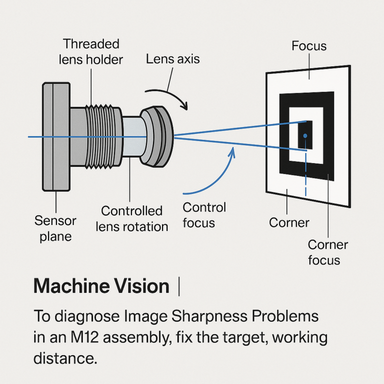
M12 Image Sharpness Problems: Diagnosing Tilt, Decentering, and Focus
11 min read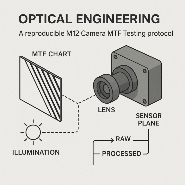
M12 Camera MTF Testing: Chart Quality, RAW Images, and Repeatability
10 min read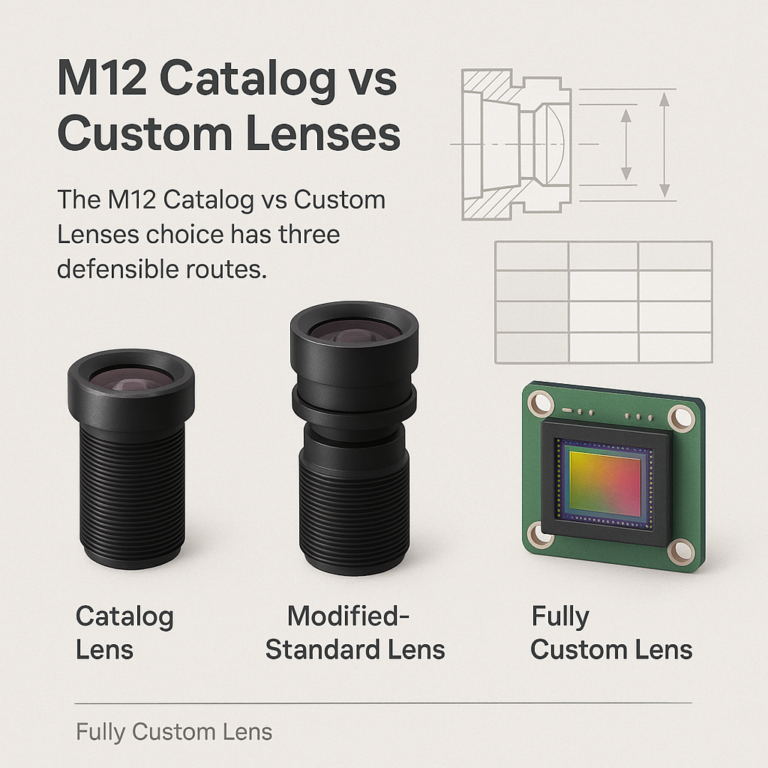
M12 Catalog vs Custom Lenses: Justifying Development for OEM Cameras
11 min readAbout SUPERIOR OPTICS
SUPERIOR OPTICS specializes in CCTV lenses, machine vision optics, and custom optical solutions for security, industrial imaging, and specialty applications. We also provide professional lens selection and application support.