M12 Sensor Coverage and Field of View: Comparing Lens Specifications
A calculation-led guide to comparing M12 lenses by active sensor area, usable image circle, field-of-view convention and working distance.
Key Takeaways
A defensible M12 Sensor Coverage decision starts with the sensor’s active width, height and diagonal—not its optical-format label or the lens focal length alone.
- Treat the M12 thread as a mechanical interface; verify image-circle coverage separately.
- Calculate the active sensor diagonal and compare it with the lens’s stated usable image circle.
- Label every field-of-view value as horizontal, vertical or diagonal before comparing lenses.
- Use sensor dimension × working distance ÷ focal length only as a first-order shortlist calculation.
- Set coverage allowances from project tolerances, distortion and corner-quality requirements rather than a universal percentage.
The Short Answer
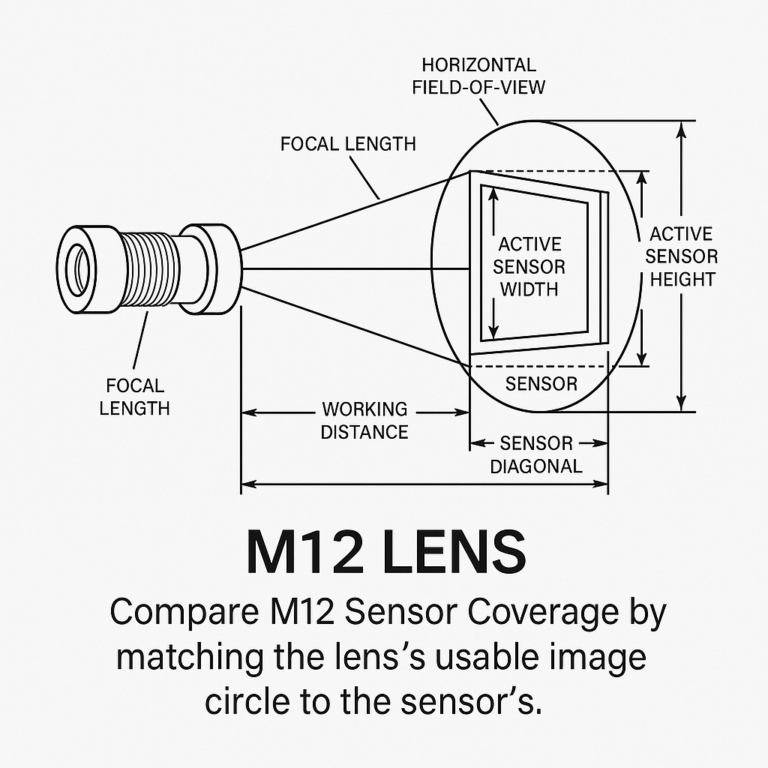
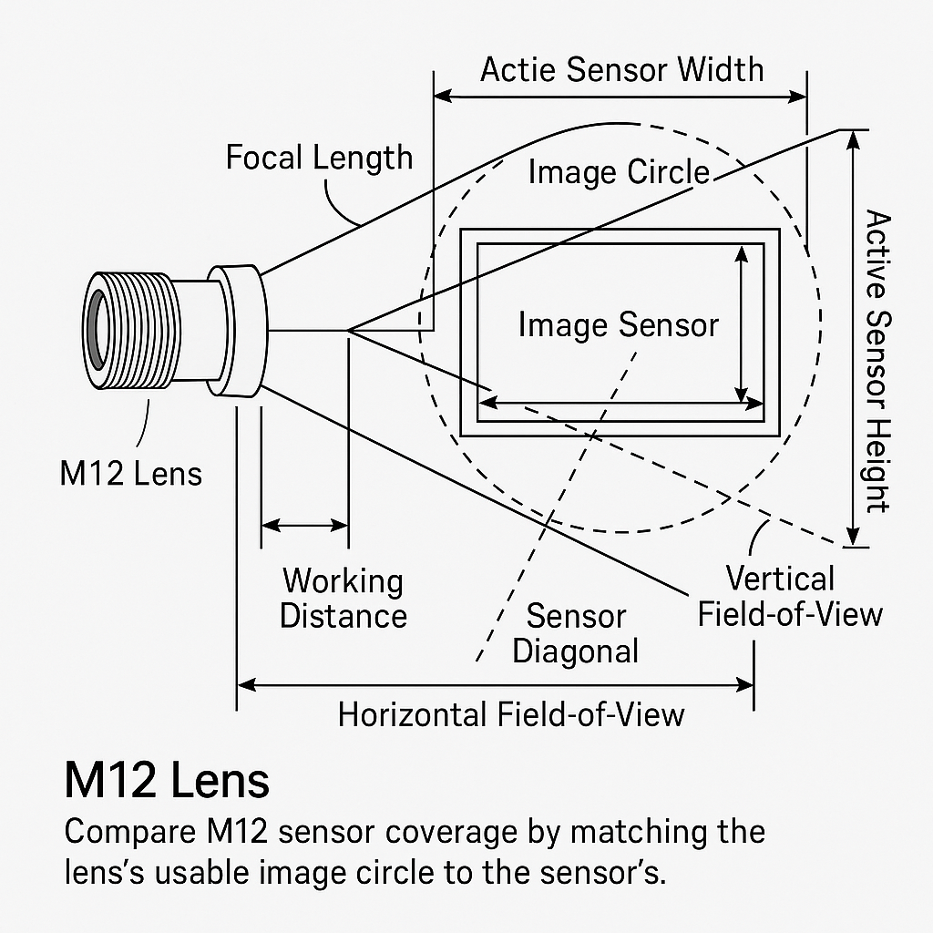
Compare M12 Sensor Coverage by matching the lens’s usable image circle to the sensor’s active width, height and diagonal, then calculate field of view in the direction the application controls. A first-order object-space estimate is active sensor dimension × working distance ÷ focal length. That calculation supports shortlisting, but it does not prove compatibility. Final approval must account for the lens’s actual distortion, focus position, corner illumination and edge image quality at the intended working-distance range.
What M12 Sensor Coverage Means for Lens Compatibility
Separate the M12 mount from the lens image circle
M12 describes the threaded lens interface; it does not establish how large a sensor the optical design can cover. Superior’s M12 lens type and specification guide describes M12/S-mount as a 12 mm threaded mount and identifies image-circle matching as a separate compatibility requirement.
A lens can therefore screw into a camera and still produce dark corners, incomplete imaging or unacceptable edge detail. Mechanical fit is necessary, not sufficient.
Use active sensor dimensions instead of optical-format labels
Obtain the active imaging width and height from the camera or sensor datasheet. Do not substitute package dimensions. Optical-format labels are also unsuitable as calculation inputs because they do not directly state the rectangular active area.
Sensor diagonal = √(active width² + active height²)
For a 5.60 × 3.15 mm example sensor, the diagonal is approximately 6.42 mm. A centered circular image circle would need to reach the rectangle’s corners, so an image-circle diameter of at least 6.42 mm is a geometric screening condition. It is not proof of acceptable corner resolution or illumination.
Define coverage by the required horizontal, vertical, or diagonal sensor area
Coverage and field of view answer different questions. Image circle asks whether the lens forms an image across the required sensor area. Field of view asks how much object space that sensor captures through the lens.
Keep the direction explicit. A conveyor-width requirement normally calls for horizontal FOV; a package-height requirement may use vertical FOV. Diagonal FOV is useful for optical comparison but rarely replaces both drawing dimensions.
The Specifications Needed to Compare an M12 Lens and Sensor
Active sensor width, height, and sensor diagonal
Record full active dimensions and any production crop or region of interest. A crop reduces the sensor dimension used for FOV calculations, although it does not change the physical sensor fitted behind the lens.
M12 lens image circle and usable image coverage
Ask whether the stated image circle means illumination only or usable imaging performance. The Commonlands IMX412 coverage reference illustrates the distinction: it compares a 7.86 mm active-area diagonal with lens coverage and notes when a circular image leaves part of the rectangular sensor outside the image circle.
For procurement, “covers the sensor” needs an acceptance condition—such as no mechanical vignetting and adequate corner detail—not merely a nominal format label.
Field-of-view convention: horizontal, vertical, or diagonal
A single FOV number is ambiguous. Datasheets and quotations should identify the sensor, direction, focus condition and working distance behind every value. The Commonlands reference lists separate horizontal, vertical and diagonal measurements because they are not interchangeable.
Working distance, focal length, distortion, and focus position
Focal length affects angular field of view, but it does not independently establish compatibility. Working distance sets the object-space span, while distortion changes where scene points appear relative to an ideal geometric projection. Focus position can also change the relevant lens-to-object geometry.
Use the broader guide to M12 lens specifications when comparing focal length, image circle, distortion and resolution fields across suppliers.
How to Calculate M12 Lens Field of View from Sensor Dimensions
Use the horizontal, vertical, or diagonal dimension that matches the requirement
Select active width for horizontal FOV, active height for vertical FOV or active diagonal for diagonal FOV. Mixing a diagonal datasheet claim with a horizontal system requirement overstates the usable width.
Apply the first-order field-of-view relationship
Object-space FOV ≈ active sensor dimension × working distance ÷ focal length
Overview AI’s M12 camera documentation publishes this quick horizontal estimate and separately provides the angular relationship 2 × arctan(sensor width ÷ (2 × focal length)). The linear estimate assumes a stated distance convention and idealized geometry; close-focus and distorted lenses require model-specific validation.
Worked calculation: estimating horizontal and vertical coverage at a stated working distance
Assume an illustrative 5.60 × 3.15 mm active area, a 6 mm lens and a 500 mm working distance:
- Horizontal FOV ≈
5.60 × 500 ÷ 6= 467 mm - Vertical FOV ≈
3.15 × 500 ÷ 6= 263 mm
These are estimates, not claimed performance for a particular lens. For a wider system-selection workflow, see how to calculate M12 lens field of view.
Validate calculated coverage against distortion, focus range, and image-quality requirements
Prototype at the minimum and maximum operating distances. Check whether the required object boundary remains visible, then assess corner illumination, resolution and geometric error. A lens may pass nominal FOV while failing inspection accuracy near the edge.
M12 Sensor Coverage Comparison Table: Dimensions, Image Circle, and FOV Assumptions
How to read the comparison table
The values below are illustrative inputs. Replace them with the exact camera, sensor, lens and mechanical-layout data for the project.
| Comparison input | Example input | Verify in | Coverage effect | Decision to document |
|---|---|---|---|---|
| Active width | 5.60 mm | Sensor datasheet | Sets horizontal calculation | Full width or crop |
| Active height | 3.15 mm | Sensor datasheet | Sets vertical calculation | Required active height |
| Active diagonal | √(5.60² + 3.15²) ≈ 6.42 mm | Calculated | Screens image-circle fit | Use active-area diagonal |
| Lens image circle | Supplier-stated usable diameter | Lens data/test | Determines corner reach | Illumination or usable quality |
| FOV convention | Horizontal | System drawing | Defines compared direction | H, V or diagonal |
| Focal length | 6 mm | Lens datasheet | Influences angular FOV | Nominal lens value |
| Working distance | 500 mm | Mechanical layout | Scales object-space FOV | Reference point and range |
| Horizontal estimate | ≈467 mm | Calculation | Estimates object width | Validate on selected lens |
| Vertical estimate | ≈263 mm | Calculation | Estimates object height | Keep separate from width |
| Coverage allowance | Project-specific | Tolerance analysis | Adds usable-area requirement | Causes and acceptance limits |
Which values must come from the camera sensor datasheet and lens datasheet
The camera documentation should supply active width, active height, pixel count and crop behavior. Lens documentation or supplier confirmation should cover image circle, focal length, distortion, focus range and applicable performance conditions. Working distance and allowable object movement belong to the machine layout, not the lens datasheet.
Why Identical Focal Length Lenses Have Different Coverage Claims
Different sensor dimensions produce different fields of view
The same lens projects onto whatever active area the camera uses. A wider sensor samples more of the image horizontally, provided the image circle and edge performance support it. Consequently, focal length comparisons are meaningful only when sensor dimensions are held constant.
Horizontal, vertical, and diagonal FOV claims are not interchangeable
Diagonal values are normally larger than either rectangular dimension for the same sensor and lens. A quotation that says only “70° FOV” cannot be compared reliably with a drawing that requires 70° horizontally.
Image-circle limits and corner performance can change usable coverage
Two lenses may share a nominal focal length while having different image circles, distortion profiles or edge quality. Commonlands states that its listed FOV data incorporate measured per-lens distortion rather than relying only on focal-length estimates. That evidence is product-specific, but it shows why nominal focal length alone cannot settle a sourcing decision.
Working-distance assumptions can make the same lens appear to cover more or less
Object-space coverage increases with distance in the first-order model. A supplier value measured at one working distance should not be transferred to another without recalculation and verification. Require the distance reference—such as lens reference position to object plane—to be recorded.
How to Shortlist M12 Lenses Without Using a Universal Coverage Margin
Start with the required object area and working-distance range
Translate the inspection or surveillance requirement into minimum horizontal and vertical object-space dimensions. Calculate both at the shortest and longest allowed working distances, then review M12 lens field of view for fixed focal length lenses against the resulting shortlist.
Confirm full active-sensor coverage before adding application-specific allowance
First establish geometric compatibility: active-area diagonal versus usable image circle. Then check whether the application can accept any corner illumination loss, resolution reduction or distortion. Those are separate approval gates.
Set allowances for alignment, object-position variation, distortion, and corner-image quality
There is no evidence-based universal margin suitable for every machine or camera. Build the allowance from tolerance contributors: camera alignment, object wander, installation variation and the minimum acceptable edge performance. This is an engineering recommendation, not a manufacturer performance claim.
Document the FOV convention and acceptance criteria in the lens selection record
Record the M12 Sensor Coverage basis, sensor mode, H/V requirements, distance range and pass/fail method. If multiple suppliers are involved, use an M12 lens RFQ and approved purchase specification so assumptions do not disappear between prototype and production.
M12 Lens Selection Checklist for OEM and Machine-Vision Projects
Camera and sensor inputs to provide
- Camera model and sensor part number
- Active width, height and operating crop
- Required horizontal and vertical FOV
- Working-distance target, range and reference point
Lens performance requirements to compare
- M12 mechanical envelope and available lens length
- Usable image circle and corner acceptance criteria
- Focal length, focus range and distortion limit
- Resolution or feature-detection requirement across the field
- Illumination wavelength and any environmental constraints
Questions to resolve before prototype approval
Ask whether the datasheet values apply at the intended focus distance, whether FOV is measured or calculated, and what “sensor coverage” means in the supplier’s terminology. When standard machine vision lens options cannot meet the image-circle, distance or edge-performance requirement, request a compatibility review or custom optical assembly quotation with these inputs attached.
Frequently Asked Questions
Can an M12 lens cover a sensor that is larger than the lens’s stated optical format?
Yes, potentially, but the format label alone cannot prove it. Compare the sensor’s active diagonal with the lens’s usable image circle, then verify corner illumination and image quality. A larger active area may extend beyond the projected circle or use corners where resolution no longer meets the application requirement.
Should image circle be specified as a diameter or as usable sensor coverage?
Specify both when possible. Diameter supports a direct geometric comparison with the active sensor diagonal, while usable coverage defines the performance condition behind that number. State whether acceptance requires illumination only, no visible vignetting, or specified corner resolution and brightness at the intended focus distance.
Which field-of-view measurement should a machine builder place on a drawing?
Place the horizontal and vertical object-space dimensions required at the inspection plane. Add diagonal FOV only if it serves a defined purpose. The drawing should also identify working distance, measurement reference, sensor mode and permitted tolerance so suppliers do not interpret an unlabeled angular value differently.
How does barrel distortion affect a calculated M12 lens field of view?
Barrel distortion moves image points away from the ideal rectilinear positions assumed by a simple focal-length calculation. The scene boundary may still be visible, but dimensional mapping and edge placement can differ from the estimate. Validate the selected lens using its distortion data or a calibrated image at operating distance.
What information should an OEM provide when requesting a custom M12 optical assembly?
Provide the camera or sensor model, active dimensions, required horizontal and vertical FOV, working-distance range, target focal length if constrained, distortion and image-quality limits, wavelength range, M12 interface details and available mechanical envelope. Include corner-performance criteria and the planned verification method rather than requesting only a sensor-format match.
Topics
Related Articles
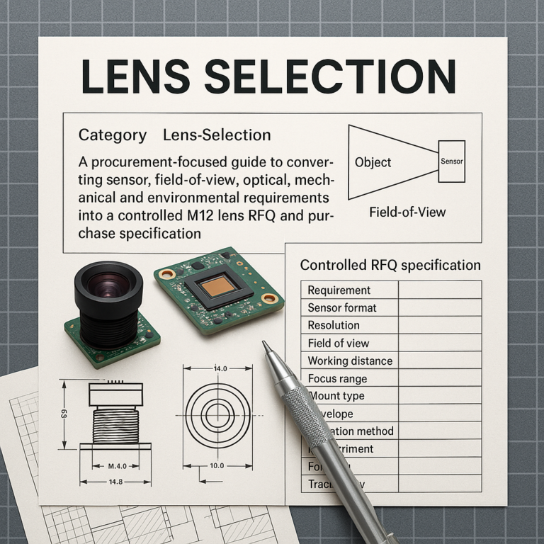
M12 Lens Selection: Building RFQ and Approved Purchase Specification
10 min read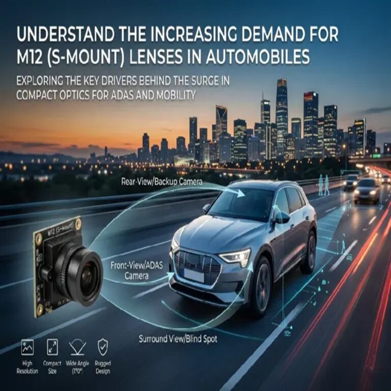
Understand the Increasing Demand for M12 (S-Mount) Lenses in Automobiles
6 min read