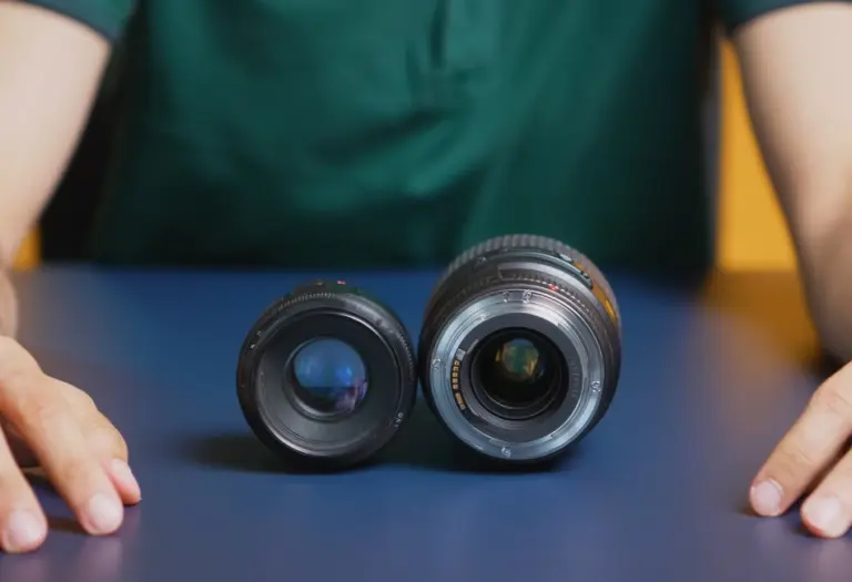
Lens Specifications Explained: Focal Length, F-Number, and MTF
A buyer-focused guide to evaluating focal length, aperture, MTF, sensor coverage, distortion, chief ray angle and working distance under comparable operating conditions.
Key Takeaways
Read Lens Specifications as an interconnected system: coverage, light collection, detail, geometry and sensor compatibility must be verified at the intended operating conditions.
- Select focal length only after defining sensor dimensions, required field of view and working distance.
- Compare MTF data at matching spatial frequencies, apertures, wavelengths and field positions.
- Verify that the stated image circle covers the sensor while still meeting corner-performance requirements.
- Treat distortion, chief ray angle and sensor-stack compatibility as separate checks rather than assuming coverage guarantees image quality.
- Put operating conditions and acceptance criteria in the RFQ when a headline datasheet value cannot establish suitability.
The Short Answer
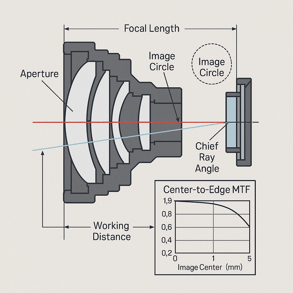
Lens Specifications describe how an optical assembly covers the sensor, frames the object, collects light, transfers contrast and preserves geometry. Focal length sets field-of-view behavior in combination with sensor size and working distance. F-number affects light collection, depth of field and diffraction. MTF reports contrast transfer at stated spatial frequencies and field positions. Buyers must also verify image circle, distortion, chief ray angle, wavelength, sensor stack and mechanical clearance. Comparisons are defensible only when the suppliers’ test definitions and operating conditions match.
A lens can cover the required sensor yet fail an inspection because edge contrast is inadequate. Another can produce a sharp image but introduce too much geometric error for measurement. Selection therefore starts with the imaging task and its tolerances—not the largest or smallest number on a datasheet.
What Are Lens Specifications?
Why a single lens specification does not predict system performance
Optical parameters describe different failure modes. Focal length does not establish sharpness; image-circle diameter does not establish corner quality; and a maximum aperture does not reveal performance when the iris is stopped down. Schneider-Kreuznach notes that lens datasheets are not standardized across vendors, making labels alone an unreliable comparison method.
How lens, sensor, illumination, distance, and application requirements interact
The recorded result depends on the lens, active sensor area, pixel sampling, spectral band, aperture, object distance and illumination geometry. Environmental windows and camera cover glass can add further optical interfaces. A valid requirement must name these conditions alongside the permitted loss of contrast or geometric accuracy.
A practical approach to how to read lens specifications
Start with four questions: What object area must fit in the frame? What detail must remain distinguishable? What geometric error is acceptable? What physical envelope is available? Use the answers to screen coverage and mechanics before comparing image quality under matched conditions.
Lens Specification Definitions at a Glance
Core optical specifications to compare on supplier datasheets
| Specification | Definition | Primary system effect | What to verify |
|---|---|---|---|
| Focal length | Optical parameter influencing angular field of view and magnification for a given sensor and distance | Scene coverage | Sensor format, field assumptions and intended distance |
| F-number | Ratio describing aperture size relative to focal length | Light collection, depth of field and diffraction | Aperture range, transmission data if supplied, and performance at the operating stop |
| MTF | Contrast preservation at defined spatial frequencies | Usable image detail across the field | Frequency, field position, aperture, wavelength and test method |
| Image circle | Image area projected at the sensor plane | Sensor coverage and vignetting risk | Diameter relative to the active sensor area |
| Resolution and distortion | Detail reproduction and geometric deviation are separate properties | Edge clarity and measurement accuracy | MTF conditions, distortion definition, value and field position |
| Chief ray angle | Angle at which the principal ray reaches a sensor field position | Off-axis sensor response | Maximum angle and camera compatibility |
| Working distance | Supplier-defined distance from a stated lens reference to the object plane | Field, focus and mechanical fit | Reference point, focus range and installation envelope |
Which specifications affect coverage, sharpness, brightness, and geometry
Coverage depends primarily on sensor format, focal length, image circle and object distance. MTF addresses contrast transfer, while F-number changes the balance among light, depth of field and diffraction. Distortion concerns geometry. These Lens Specifications overlap operationally, but they are not substitutes for one another.
Focal Length Explained: Field of View and Magnification
How focal length changes field of view
For the same sensor and object distance, changing focal length changes angular coverage and image magnification. A shorter or longer value cannot be called better without a target field of view. Applications needing installation adjustment may use varifocal lens options; stable, repeatable framing often favors a fixed configuration.
Focal length, sensor format, and effective image coverage
The focal-length value must be interpreted with the active sensor dimensions. Moving the same lens to a different sensor format changes how much of the projected image is recorded, even though the engraved focal length remains unchanged.
Why focal length must be evaluated with working distance
Distance changes framing and focus conditions. A candidate should be assessed at the actual object plane, not only at a nominal catalog distance. Also check whether focusing changes the mechanical length or usable magnification range.
F-Number Definition: Aperture, Light Collection, and Depth of Field
How F-number affects image brightness
The F-number relates focal length to effective aperture size. Opening the aperture generally increases light collection, but datasheet F-number alone is not a transmission measurement. If exposure margin matters, request spectral transmission or system-level illumination data when available.
The trade-off between aperture, depth of field, and diffraction
A wider aperture can improve light collection while reducing depth of field and exposing more off-axis aberration. Stopping down may increase usable depth and can reduce mechanical vignetting, but diffraction eventually limits transferred detail. The intended stop therefore belongs in every MTF comparison.
Fixed-aperture and adjustable-aperture considerations
A fixed stop reduces setup variability where illumination and geometry are controlled. An adjustable iris supports commissioning and changing light levels, but it introduces another setting that must be locked or documented. Buyers comparing fixed focal length lenses should still confirm whether the aperture itself is fixed or adjustable.
MTF Lens Performance: How to Evaluate Sharpness
What an MTF chart measures
Modulation transfer function compares image-plane modulation with object modulation as spatial frequency changes. The manufacturer’s guide to optical datasheets states that MTF is commonly presented against frequency in line pairs per millimeter and generally declines as frequency rises.
Center-to-edge MTF and field-dependent performance
Center performance cannot establish corner performance. Review the specified field positions and orientation of the plotted data. For an inspection feature near the frame boundary, uniformity may matter more than a higher center result.
Spatial frequency, sensor pixel size, and usable image detail
The relevant frequency follows from the feature to be detected and the sensor’s sampling capability. A high-frequency curve has little buyer value unless it corresponds to the camera and task. The practical issue is system contrast at the feature scale, not a standalone resolution label.
Why MTF results should be compared under matching test conditions
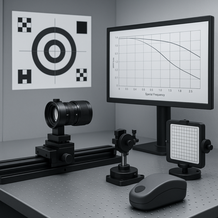
Geometrical and diffraction-aware MTF methods can produce different values. Wavelength, focus, aperture, field location and test configuration also matter. Compare curves only when those conditions are equivalent; otherwise, request aligned data. Production requirements can then be converted into optical lens quality control for MTF and distortion criteria.
Image Circle and Sensor Compatibility
What image circle means
Image circle is the projected image area available at the sensor plane. Some industrial datasheets express maximum sensor size as an image-circle diameter. That indicates nominal coverage, not guaranteed edge illumination or sharpness.
How to avoid vignetting and corner performance loss
Confirm both mechanical clearance and relative illumination across the active area. A lens may technically cover the sensor while producing dark or low-contrast corners. Aperture, focus position and mechanical components can change the result.
Matching lens image circle to the active sensor area
Use the sensor’s active diagonal and dimensions rather than a format nickname alone. Then verify corner MTF, illumination and distortion at the operating aperture. Extra circle diameter is useful only if the required field remains within the lens’s qualified performance region.
Lens Resolution and Distortion in Real Imaging Systems
Lens resolution versus sensor resolution
Lens and sensor limits combine at system level. A high-pixel-count camera cannot recover contrast the lens fails to transfer, while a higher-performing lens cannot create sensor samples that were never recorded. Match both to the smallest application-relevant feature.
Barrel, pincushion, and mustache distortion
Distortion changes geometric representation and can vary with image height and magnification. Supplier conventions also matter: Schneider-Kreuznach distinguishes lens geometric distortion from TV distortion and associates negative and positive geometric values with barrel and pincushion forms. Complex distortion may change character across the field.
When distortion correction is acceptable and when optical correction matters
Software correction can be reasonable when calibration is stable and resampling is permitted. Optical correction carries more weight when raw geometry must be preserved, edge pixels are scarce, calibration cannot be maintained or processing latency is constrained. This is an application decision rather than a universal ranking.
Chief Ray Angle and Sensor Stack Compatibility
What chief ray angle means at the sensor plane
Chief ray angle describes the principal ray’s incidence at a sensor field position. The angle normally varies across the image, so a single maximum value needs its field definition.
Why sensor microlenses and cover glass can affect off-axis performance
Sensor microlenses, protective glass and filters influence how oblique rays reach the photosensitive area. Coverage alone therefore cannot prove camera compatibility. Possible symptoms of mismatch include field-dependent color, illumination or sharpness loss; these outcomes should be treated as risks to verify, not assumed results.
When to review chief ray angle with the camera supplier
Review it when the sensor vendor publishes angular acceptance guidance, the lens has a short back-focal configuration, corners are performance-sensitive or the camera uses a significant filter stack. Ask both suppliers to reference the same wavelength and sensor field position.
Working Distance, Object Space, and Mechanical Constraints
Defining working distance from the correct reference point
Working distance is meaningful only with a reference. One supplier may measure from the first mechanical element, while another may use a different datum. Record the reference in drawings and RFQs rather than copying an unlabeled number.
Working distance, field of view, and depth of field trade-offs
Changing distance affects framing, magnification and focus. If object position varies, evaluate the full travel range and the acceptable blur at both limits. The guide to machine vision lens focal length and working distance selection provides a practical next step for system layout.
Accounting for housing, protective windows, and installation clearance
Reserve space for the lens barrel, focus or iris access, mount engagement, cables, seals and any protective window. A window can also alter optical performance, particularly when tilted or used outside the wavelength range for which its coating was selected.
How to Compare Lens Datasheets for an OEM Application
Build a requirements checklist before comparing lenses
List the sensor part number, active area, object field, distance range, spectral band, illumination, aperture, required feature size, distortion tolerance, mount and envelope. Add environmental and production-volume requirements. Without these inputs, the shortlist reflects catalog availability rather than application fit.
Compare specifications using the same sensor, wavelength, aperture, and field conditions
Normalize definitions before ranking Lens Specifications. Check whether MTF is measured or calculated, what type is shown, whether distortion is geometric or TV distortion, and which magnification applies. Mark missing conditions as unresolved; do not silently treat them as equivalent.
Decision example: if one lens has stronger center MTF but weaker edge data at the relevant frequency, it is not automatically preferable. A centrally located recognition task may favor it. An inspection spanning the full frame may favor the more uniform candidate. This is an engineering inference from field-dependent performance, not a universal rule.
Identify when a stock lens is appropriate versus a custom optical assembly
A stock lens is appropriate when its qualified operating range satisfies optical, mechanical and commercial requirements without unstable workarounds. Customization becomes defensible when sensor coverage, spectrum, packaging or controlled production performance cannot be reconciled. The same decision logic is illustrated in the comparison of stock versus custom SWIR lenses.
Lens Specification Checklist for Technical Buyers
Coverage and geometry requirements
- Active sensor dimensions and required object field
- Distance and focus range, with stated reference points
- Image circle, relative illumination and permitted distortion
- Feature locations, including edge-of-field regions
Image-quality and sensor-matching requirements
- MTF frequency, threshold, field points, aperture and wavelength
- Sensor pixel architecture, cover glass and chief-ray constraints
- Spectral transmission and illumination conditions
- Acceptable variation across samples and production lots
Mechanical, environmental, and manufacturing requirements
- Mount, back clearance, barrel envelope and adjustment locking
- Temperature, vibration, sealing and window configuration
- Inspection method, sampling plan and acceptance criteria
- Forecast volume, change control and traceability needs
For a defensible shortlist, request technical guidance that matches Lens Specifications to the sensor, field of view, working distance, wavelength and environment. If no stock configuration meets the acceptance criteria, discuss an RFQ for a custom optical assembly rather than relaxing requirements informally.
Frequently Asked Questions
What lens specifications should be prioritized for a low-light imaging application?
Prioritize aperture range, spectral transmission when supplied, image-circle coverage and MTF at the intended operating aperture and wavelength. Also check available illumination, exposure time, sensor response and required depth of field. A low F-number can collect more light, but it does not by itself guarantee adequate edge sharpness or system sensitivity.
Can two lenses with the same focal length produce different image quality?
Yes. Equal focal length does not establish equal MTF, distortion, relative illumination, spectral transmission or corner performance. The lenses may also use different aperture ranges and image circles. Compare them on the same sensor at matching wavelength, focus, aperture, object distance, spatial frequency and field position.
How do I know whether a lens is compatible with a camera sensor?
Check that the image circle covers the sensor’s active dimensions, then verify mount, flange geometry, focus range, corner illumination, MTF and distortion. Review chief ray angle against sensor guidance and account for cover glass or filters. Compatibility means meeting the application tolerance, not merely producing an image without hard vignetting.
Should OEM buyers request lens performance data at multiple apertures?
Yes, when the operating aperture may change or has not been fixed. MTF, depth of field, illumination and aberration balance can vary with aperture, while stopping down introduces diffraction trade-offs. Request data at the intended stops under matching wavelength, focus, field and test-method conditions rather than extrapolating from maximum-aperture performance.
What information should be included in an RFQ for a custom optical assembly?
Include the sensor part number and active area, required field of view, object-distance range, wavelength band, illumination, aperture, MTF target and field positions. Add distortion limits, chief-ray constraints, mount, mechanical envelope, environmental conditions, protective windows, expected volume, inspection method, acceptance criteria and any adjustment or locking requirements.
Topics
Related Articles
Optical Lens Quality Control: MTF, Distortion, and Centering
11 min read
Custom Lens RFQ Checklist: Requirements OEM Buyers Must Define
10 min read