Line Scan vs Area Scan: Choosing an Industrial Imaging System
Compare line and area scan architectures by production flow, coverage, synchronization, lighting, integration risk and optical requirements.
Key Takeaways
The Line Scan vs Area Scan decision starts with how the product moves and how much surface must be inspected—not with camera price or nominal resolution.
- Choose line scan when controlled motion can carry a continuous, cylindrical or oversized surface past a narrow acquisition line.
- Choose area scan when the system must capture a complete two-dimensional scene or inspect discrete parts within a defined field of view.
- Calculate object-space pixel density across the required field before comparing camera megapixels or line counts.
- Treat motion synchronization, illumination and data throughput as architecture-level requirements rather than commissioning details.
- Validate borderline applications with representative parts, production speeds, defects, lighting and candidate optics before releasing hardware.
The Short Answer
Choose line scan for continuous materials, rotating surfaces or objects whose required image length would exceed a practical area-scan frame. Choose area scan for complete scenes, discrete parts and stationary or momentarily stationary inspections. The Line Scan vs Area Scan decision must also account for object-space resolution, speed variation, synchronization, lighting and processing load. Line scan can provide continuous coverage along the direction of travel, but usually demands tighter motion coordination. Area scan is generally simpler to align, yet a low-cost frame camera becomes a poor investment if its field of view cannot preserve the required defect detail.
Line Scan vs Area Scan: The Core Difference
How area scan cameras capture a complete image frame
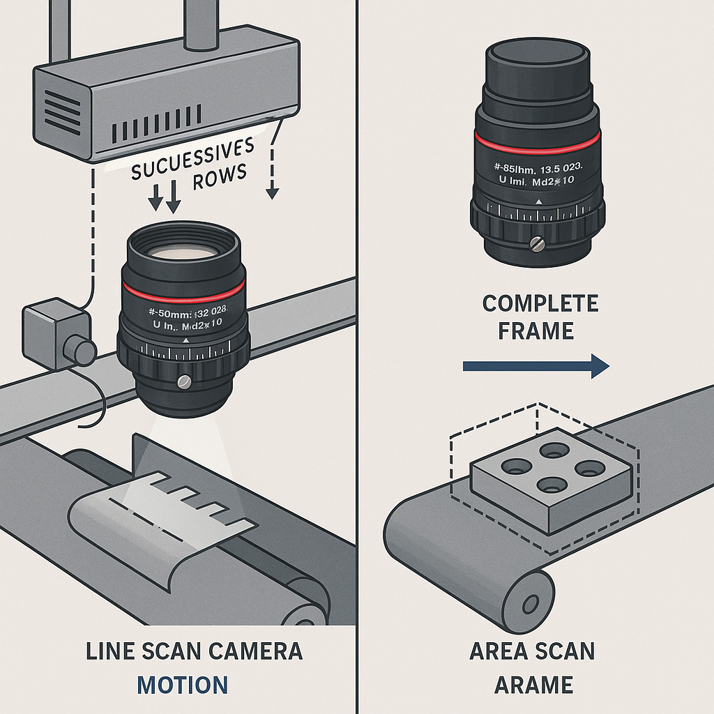
An area scan camera exposes a rectangular pixel array to capture a two-dimensional frame. It suits a stationary part, a part paused at an inspection station or a moving part that can be frozen adequately by exposure and lighting. The object still has to fit within the field of view at the required resolution. These acquisition characteristics are documented in KEYENCE’s line and area scan overview.
How line scan cameras build an image one line at a time
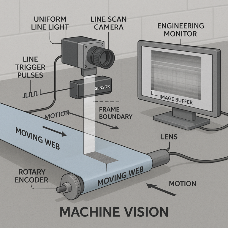
A line scan camera acquires a narrow pixel row while the product—or camera—moves. Software assembles successive rows into a two-dimensional image. Image length is therefore governed by acquisition duration and motion rather than a fixed frame height, making the architecture useful for webs, rolls, cylinders and oversized surfaces.
Why image acquisition method affects system architecture
Area scan concentrates acquisition into frames and trigger events. Line scan makes motion part of image formation: line rate, transport speed and spatial sampling must remain coordinated. That difference propagates into encoder selection, lighting geometry, interfaces, processing and commissioning.
Line Scan Camera vs Area Scan Camera: Comparison Table
| Decision Factor | Line Scan Camera | Area Scan Camera | Architecture Implication |
|---|---|---|---|
| Image acquisition method | Successive lines assembled into an image | Complete two-dimensional frame per exposure | Motion forms the second line-scan image axis |
| Best-fit production flow | Continuous or controlled travel | Discrete, stationary or indexed parts | Start with material handling, not camera format |
| Object motion requirements | Repeatable motion is normally required | Motion may be absent, indexed or frozen | Line scan adds synchronization work |
| Inspection coverage | Full width plus extended travel length | Fixed rectangular field | Long products may exceed one frame |
| Continuous materials | Strong fit for webs, sheet and film | Possible when framing and overlap are sufficient | Area scan may require multiple frames or cameras |
| Discrete parts | Works when travel is controlled | Natural fit for complete-part views | Presentation variability favors frame context |
| Synchronization | Line timing often follows motion | Part trigger initiates a frame | Controls architecture differs materially |
| Lighting | Uniform illumination along the acquisition line | Broader lighting geometries are available | Illumination must match capture geometry |
| Integration complexity | Usually higher motion and timing burden | Generally easier setup and alignment | Camera cost alone is incomplete TCO evidence |
| Primary boundary | Weak motion control can distort geometry | Finite frame and pixel count limit coverage | Validate the dominant failure mode |
Decision summary: choose line scan for controlled continuous motion and extended surfaces. Choose area scan for complete scenes and discrete parts, provided the frame preserves the required feature detail.
Match the Camera Architecture to Production Flow
Continuous web, sheet and roll-to-roll production
Paper, film, foil and similar materials naturally present the surface as a continuous stream. One line-scan camera can cover the width while transport supplies the second image dimension. The design still needs evidence that line rate, interface bandwidth, illumination and processing can support maximum production speed.
Discrete parts moving through a fixed inspection station
Area scan is usually the lower-risk starting point when each part can be triggered within a known inspection window. A single frame can also be divided into regions of interest for code, feature or assembly checks, as described in this area and line scan technical comparison.
Wide-format, long-length and cylindrical surfaces
A long object can be reconstructed without imposing a conventional frame-height limit. A rotating cylinder can likewise be represented as an unwrapped surface if rotation and acquisition remain coordinated. Width remains finite, so the sensor, lens image circle and required object-space sampling still constrain the design.
Stop-and-go production and variable part presentation
Indexed motion favors area scan because the camera can acquire while the part is stationary. Variable pose also benefits from two-dimensional scene context. Line scan can inspect discrete objects, but engineering inference suggests that inconsistent velocity or orientation increases controls and algorithm risk unless handling is improved.
Inspection Coverage, Resolution and Defect Requirements
When full-width coverage favors line scan imaging
Line scan is attractive when the camera can span the entire inspection width and production motion exposes every surface segment. Multiple area cameras might also cover the width, but seams, overlapping fields and separate calibrations become buyer-facing integration issues.
When two-dimensional scene capture favors area scan
Assembly verification, presence checks and feature relationships often depend on seeing the full scene at once. Area scan preserves that context in one frame. Fast motion can still cause blur, so exposure and lighting must be assessed at actual line speed rather than from static samples.
Relating field of view, pixel density and minimum detectable feature
A useful first calculation is:
object-space pixel density = active pixels across the inspection axis ÷ field width
For a hypothetical 4,000-pixel axis covering 400 mm, the nominal sampling is 10 pixels/mm, or 0.1 mm per pixel. That arithmetic is not a detection guarantee. Lens contrast, focus, illumination, defect contrast, vibration and algorithms determine whether the smallest rejectable feature is distinguishable. Confirm the acceptance threshold with representative defects.
Evaluating surface, edge, print and assembly inspection needs
Surface inspection usually prioritizes uninterrupted coverage and stable illumination. Edge inspection may impose depth-of-field or viewing-angle constraints. Print inspection needs enough sampling and contrast for the smallest relevant mark, while assembly inspection may require scene context. The defect specification should therefore precede camera procurement.
Motion Control, Lighting and Synchronization Requirements
Encoder synchronization and line-rate stability
Line acquisition is commonly synchronized to an encoder that tracks transport motion. Encoder-based timing helps keep spatial sampling tied to travel when speed changes. It is not automatically mandatory: a stable process may use a fixed line rate, but the distortion risk must be accepted and tested.
Object speed variation and image distortion risk
If travel per acquired line changes while line timing remains fixed, reconstructed features can stretch or compress along the motion axis. Slippage, vibration and encoder placement can also weaken the relationship between measured and actual product movement. The Line Scan vs Area Scan choice therefore includes a controls audit, not just an imaging comparison.
Lighting uniformity across the inspection width
A line-scan illuminator must deliver adequate, consistent light along the acquisition line. Uneven output can resemble product variation or reduce defect contrast. Area scan supports broader lighting configurations, but uniformity, glare and exposure remain application-specific constraints. This distinction is also summarized in ELVOTEC’s camera architecture guide.
Triggering considerations for area scan machine vision inspection
The trigger should place the complete part inside the field of view and within the acceptable exposure window. Sensor latency, conveyor variation and part spacing belong in the timing budget. Strobe illumination or a short exposure can reduce apparent motion, subject to available light and camera capability.
Integration Complexity and Total System Trade-Offs
Camera, frame grabber, interface and processing considerations
Compare sustained data generation, interface capacity, host processing and storage—not only sensor resolution. Some implementations require a frame grabber; others use camera interfaces supported directly by the host. The correct configuration depends on the selected camera and throughput, so procurement documents should assign compatibility responsibility explicitly.
Mechanical alignment and optical working-distance constraints
Line scan demands alignment between the sensor line, illuminated strip and travel direction. Both architectures need stable working distance, focus and field coverage. Mount stiffness and service access can be as consequential as nominal optical specifications when a production machine vibrates or requires frequent changeovers.
Commissioning risk in line scan systems
The extra risk is concentrated at subsystem boundaries: camera timing versus motion, illumination versus exposure, and processing versus data rate. A factory acceptance plan should include minimum and maximum speed, acceleration, normal web wander or part variation, and known defect samples.
When a lower-cost area scan arrangement may create inspection risk
An area camera may cost less to integrate, but it is not lower cost if wider coverage forces inadequate pixel density or leaves gaps. Conversely, line scan adds avoidable complexity when a complete part already fits comfortably inside one frame. Total cost should include controls, lighting, calibration, software and commissioning time.
Line Scan Imaging Applications and Area Scan Camera Applications
Typical line scan imaging applications
Common fits include continuous web inspection, long printed material, sheet surfaces and rotating cylindrical products. The shared condition is controlled relative motion through a narrow imaging zone—not speed alone.
Typical area scan camera applications
Area scan commonly supports presence checks, code reading, measurement and assembly verification for discrete parts. It is also appropriate for stationary inspection and indexed machines when the necessary scene fits within one frame.
Applications where either architecture can work
A conveyor carrying separated products may support either approach. Area scan offers whole-object context; line scan may offer uninterrupted surface coverage. Compare both against the same defect library, speed range, field width, allowable installation envelope and processing requirement.
When multispectral or SWIR imaging changes the selection process
If visible contrast is insufficient, spectral response may become the first decision. Review whether SWIR imaging for moisture, defects and material inspection systems addresses the target material. An InGaAs design also needs a compatible sensor format, wavelength range and lens; this guide explains how to select a SWIR lens for an InGaAs camera inspection system.
How to Choose Between Line Scan and Area Scan Cameras
Decision questions for OEM buyers and machine builders
Ask what moves, whether velocity is measurable, how wide and long the inspection region is, and which smallest defect drives acceptance. Then document line speed, pose variation, available working distance, spectral band, environmental constraints, data retention and permissible false-accept risk.
When to select line scan
Select it when extended surface coverage is required and controlled motion can reliably form the second image axis. It is especially defensible when a frame boundary would interrupt inspection or when a cylindrical surface must be unwrapped.
When to select area scan
Select it when whole-scene context matters, objects are stationary or indexed, or a discrete part fits within the required field at adequate sampling. The architecture is also preferable when motion synchronization would add risk without improving coverage.
When to validate the architecture with an imaging feasibility test
Test when defect contrast is uncertain, speed varies, the field is unusually wide, reflective surfaces complicate illumination, or either option sits near its resolution boundary. Use production-representative parts and reject samples. A static image alone cannot validate a motion-dependent inspection.
Select Optics After Defining the Imaging Architecture
Lens requirements for line scan cameras
The lens must cover the full sensor line and support the required sampling across the field. Review image circle, sensor length, mount, working distance, magnification and contrast performance when comparing line scan lenses. Edge performance matters because inspection spans the line rather than only its center.
Lens requirements for area scan cameras
An area-scan lens must cover both sensor dimensions without unacceptable loss of usable detail. Field of view, sensor format and working distance establish the initial focal-length requirement. Distortion, depth of field and corner performance then need to be evaluated against the measurement or inspection task.
When a standard machine vision lens is sufficient
Catalog machine vision lenses are a defensible choice when sensor coverage, mount, field, spectral response and mechanical envelope align with published specifications. That conclusion still requires an image-quality check at the intended aperture, distance and illumination.
When a custom optical assembly may be justified
Custom engineering becomes relevant when packaging, sensor coverage, spectral range, environmental sealing or performance targets cannot be reconciled with catalog options. The commercial comparison should include recurring volume and qualification effort; this overview of COTS vs custom optical lenses frames that trade-off. Before commitment, request a feasibility review covering architecture, sensor format, motion, illumination and optics.
Frequently Asked Questions
Can an area scan camera inspect a continuous web?
Yes, if each frame covers the required width and successive frames provide complete coverage at production speed. The design must account for frame rate, overlap or gaps, exposure, data throughput and pixel density. For very long continuous images, line scan may avoid frame-boundary and stitching complications.
Do line scan cameras always require an encoder?
No. A fixed line rate can work when transport speed is sufficiently stable and geometric accuracy requirements are tolerant. An encoder is commonly used because it ties acquisition timing to measured motion. If speed varies without corresponding timing correction, the reconstructed image can stretch or compress along the travel direction.
What causes distortion in a line scan image?
Distortion commonly results when object travel per acquired line is inconsistent. Speed variation, slippage, vibration, poor encoder placement or incorrect line-rate settings can alter reconstructed geometry. Optical distortion and alignment errors may add separate effects, so troubleshooting should distinguish motion-axis deformation from lens or mounting problems.
Can the same lens be used with both line scan and area scan cameras?
Sometimes, but compatibility cannot be assumed. The lens must cover the relevant sensor dimensions, mount correctly and deliver adequate resolution, working distance, magnification and spectral transmission. A lens suitable for a short line sensor may not cover the corners of a rectangular area sensor, or vice versa.
When should an OEM use a custom lens assembly for an industrial imaging system?
Use custom optics when catalog lenses cannot meet the combined sensor coverage, field, working distance, spectral, packaging, sealing or image-quality requirements. The decision should also consider production volume, qualification effort and lifecycle support. A feasibility study can determine whether customization removes a real constraint or merely adds cost and schedule risk.
Topics
Related Articles