


How to Calculate Line Scan Camera Field of View and Working Distance
An engineering guide to calculating cross-web sampling, optical magnification, preliminary focal length, line rate and encoder trigger spacing for line-scan inspection.
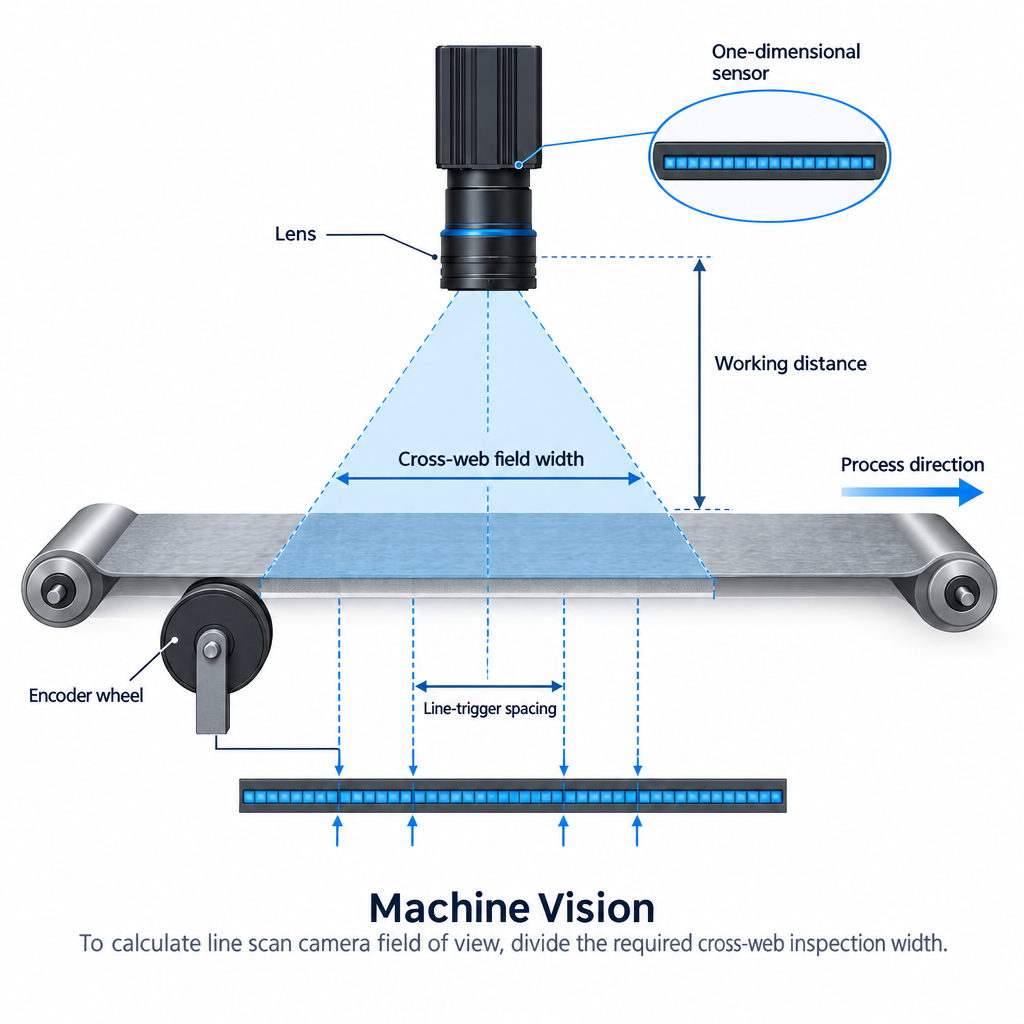
Key Takeaways
A defensible line scan camera field of view calculation treats cross-web optics and process-direction timing as separate design problems, then verifies both against the selected camera, lens and encoder.
- Divide inspection width by usable pixel count to determine cross-web object sampling.
- Calculate optical magnification as sensor active length divided by object field width.
- Do not derive working distance from field of view alone; it depends on the selected lens and finite-conjugate geometry.
- Set line rate from material speed and required process-direction sampling, not from camera resolution alone.
- Approve a lens only after checking image coverage, edge performance, distortion, wavelength, aperture and mechanical clearance.
The Short Answer
To calculate line scan camera field of view, divide the required cross-web inspection width by the usable sensor pixel count to find object-space sampling. Calculate magnification by dividing sensor active length by object field width. Separately, divide material speed by the desired process-direction sampling to obtain the required line rate. Working distance cannot be determined from field of view alone: use the calculated magnification with a candidate lens’s finite-conjugate data, principal-plane location and mechanical envelope. Finally, verify image-circle coverage, edge resolution, distortion, illumination and encoder timing on the physical system.
Line-scan design has two independent axes. The lens and sensor establish the width captured across the material. Motion and triggering build the second dimension one line at a time. Treating the system like an area camera can produce correct cross-web resolution but stretched, compressed or incomplete images in the direction of travel.
Quick Answer: Inputs Needed for a Line Scan Camera Field of View Calculation
The five core inputs
Start with the required scan width, sensor active length, usable pixel count, target object sampling and permitted working-distance range. Pixel pitch is also needed if active length is not stated:
Sensor active length, S = pixel count, N × pixel pitch, p
Use consistent units. A pitch entered in micrometres must be converted before combining it with dimensions in millimetres.
Why the two dimensions are independent
Cross-web sampling comes from optical projection onto the sensor line. Process-direction sampling is the material movement between consecutive acquisitions. Square object-space sampling requires both values to be equal, but that is a design choice rather than a universal requirement.
Formula library and limits
| Calculation | Formula | Output | Boundary condition |
|---|---|---|---|
| Sensor length | S = N × p | Sensor active length | Use active, not package, dimensions |
| Cross-web sampling | sₓ = W ÷ N | Object distance per pixel | Assumes the stated width fills the usable line |
| Magnification | M = S ÷ W | Image/object ratio | Verify within the lens’s rated conjugate range |
| Process sampling | sᵧ = v ÷ R | Travel per acquired line | Speed and line rate must use compatible units |
| Required line rate | R = v ÷ sᵧ | Lines per second | Must remain within camera and interface limits |
| Encoder pulses per line | Pₗ = E × sᵧ | Pulses per trigger | E is effective pulses per unit travel |
| Thin-lens estimate | f = M × u ÷ (1 + M) | Approximate focal length | u is measured from the object-side principal plane, not the lens housing |
These equations are geometric derivations for preliminary sizing. They do not replace model-specific camera timing or lens data.
Define Cross-Web Field of View and Process-Direction Sampling
Cross-web field of view
The cross-web width, W, is the object span projected onto the active sensor line. If the product can wander laterally, the optical field must include that movement plus any required edge margin. Using nominal product width alone can leave edge defects outside the acquired line.
Process-direction sampling
If material velocity is v and acquisition rate is R, travel per line is sᵧ = v/R. This value changes when speed changes unless encoder-triggered acquisition tracks the motion. A free-running line rate may be adequate at tightly controlled speed; an encoder is generally the more defensible choice when speed varies.
Square versus rectangular sampling
Square sampling is useful when dimensions are measured in both axes or algorithms assume equal scale. Rectangular sampling can be valid when defects are strongly directional, data volume is constrained or one axis needs less detail. The acceptance test must then preserve separate x- and y-axis calibration values.
Calculate Cross-Web Resolution, Sensor Coverage, and Magnification
Object-space pixel size and defect target
For usable pixel count N across width W, cross-web sampling is W/N. A defect criterion must state how many samples are required across the feature. That number is application-specific: contrast, blur, noise and the detection algorithm prevent a universal pixels-per-defect rule.
For procurement, write the requirement as an acceptance condition—for example, “resolve the specified target at the field edge”—rather than relying only on nominal sampling.
Magnification and sensor-side sampling
Magnification is M = S/W. The same result follows from sensor pixel pitch divided by object-space pixel size. The equality is also a useful unit check.
Pixel count alone does not establish sensor size. Two sensors with equal counts but different pitches require different image coverage. The relationship is detailed in line scan sensor length and lens coverage.
Estimate Line Scan Camera Working Distance and Lens Focal Length
A first-pass lens calculation
If object distance u is known from the object-side principal plane, the thin-lens relationship gives f = Mu/(1 + M). This can identify a plausible focal-length class, but it is not a final line scan camera lens calculation.
Mechanical working distance is commonly specified from a physical lens reference, while the equation uses an optical principal plane that may sit elsewhere. Internal focusing and multi-element construction further limit the estimate. Consequently, field width and sensor size do not uniquely determine working distance.
Datasheet and packaging checks
Select candidate machine vision lenses using their stated magnification, object distance, image coverage and mount data. Reserve clearance for the housing, illumination, focus adjustment, cable routing and protective windows. A mathematically feasible object distance can still be mechanically unusable.
Calculate Line Rate, Encoder Trigger Spacing, and Motion-Direction Resolution
Required line rate
With desired travel per line sᵧ, required line rate is R = v/sᵧ. Check the result against the camera’s operating mode, bit depth, exposure controls and data interface. Model-specific limits are unresolved until a current camera manual is selected.
Encoder scaling
If the effective encoder scale is E pulses per millimetre, pulses per line are E × sᵧ. A non-integer result requires a controller capable of fractional scaling or an intentionally adjusted sampling interval. Rounding a divider without recalculating image scale introduces systematic process-direction error.
Slip between an encoder wheel and material, shaft runout, vibration, acceleration and missed pulses can all disturb spacing. Commissioning should compare commanded travel with a traceable physical target rather than assuming the encoder’s nominal scale is exact.
Exposure and motion blur
Line period is 1/R. Exposure must fit the camera’s timing mode and produce acceptable motion blur. A first-order blur estimate is v × exposure time in object space. Shortening exposure reduces blur but also reduces collected light, so illumination margin and aperture cannot be separated from timing.
Validate the Lens-Camera Pair Before Finalizing the Design
The lens must cover the active line with acceptable performance at the centre and edges. Image-circle diameter alone does not establish edge modulation, relative illumination or distortion. Review the actual sensor length, wavelength, aperture and magnification using line scan lens selection for large sensors.
| Decision factor | Conventional line-scan lens | Telecentric line-scan lens | Buyer consequence |
|---|---|---|---|
| Height variation | Magnification can change with object distance | Designed to reduce perspective-related scale change within its rated range | Use telecentricity when dimensional error from height is unacceptable |
| Packaging | Often smaller and more flexible | Commonly larger for a given object field | Check installation envelope early |
| Calibration | Distortion and perspective may need correction | Still requires calibration and verification | Telecentric does not mean calibration-free |
| Cost decision | Suitable for many presence and surface inspections | Justified by measurement stability requirements | Specify allowable error before choosing architecture |
Other go/no-go checks include MTF at the relevant spatial frequency, edge illumination, distortion, depth variation, aperture, diffraction sensitivity, wavelength response, mount, clear aperture and protective-window effects. These require lens-specific evidence or prototype measurements; nominal focal length cannot answer them.
Worked Example: Wide-Web Line Scan Inspection Calculation
This is an illustrative calculation, not a customer result or documented product specification.
Assumptions
A hypothetical system has a 1,000 mm inspection width, an 8,192-pixel sensor with 7 µm pitch, material speed of 2,000 mm/s and a 0.5 mm defect target. The provisional acceptance assumption is at least four samples across that target. A 500 mm object distance from the principal plane is used only to demonstrate the thin-lens estimate.
Cross-web results
Sensor length is 8,192 × 0.007 = 57.344 mm. Cross-web sampling is 1,000/8,192 = 0.1221 mm per pixel, or about 122 µm. The 0.5 mm target spans approximately 4.1 samples before optical blur and contrast losses, so nominal sampling passes the assumed four-sample screen.
Magnification is 57.344/1,000 = 0.05734×. This line scan camera field of view therefore needs a lens that supports that magnification while covering at least the 57.344 mm active line with acceptable edge quality.
Process-direction and focal-length results
For square sampling, required line rate is 2,000/0.1221 ≈ 16,384 lines/s. The line period is about 61 µs. With an encoder scale of 100 pulses/mm, the controller receives about 12.21 pulses per desired line, so a simple integer divider cannot reproduce the target exactly.
Using the assumed principal-plane object distance, the preliminary focal length is 0.05734 × 500/(1.05734) ≈ 27.1 mm. That number is only a search starting point. Final approval depends on the real lens’s principal planes, rated conjugates, housing reference, focus range and image performance.
Go/no-go review
The sampling and nominal line rate pass the stated assumptions. Lens coverage, edge contrast, distortion, illumination, exposure, interface bandwidth and physical working distance remain open. The design should not move to production procurement until those items have measured acceptance criteria.
Turn the Calculation Into a Lens RFQ and Commissioning Plan
An RFQ should identify the camera and sensor model, active length, pixel pitch, required field width, sampling target, speed range, encoder scale, working-distance window, depth variation, wavelength, aperture constraints, mount and available package volume. Add quantified limits for distortion, edge resolution and relative illumination when those parameters affect acceptance.
For non-standard geometry, wavelength or packaging, describe the requirement when requesting custom optical lens assemblies. Supplier review should separate calculated targets from guaranteed specifications and from values that require prototype testing.
Prototype acceptance should cover:
- Full-width coverage at minimum and maximum object position.
- Centre and edge target visibility at the intended aperture and wavelength.
- Calibrated cross-web and process-direction scale.
- Trigger stability across the full speed and acceleration range.
- Exposure margin, illumination uniformity and thermal operating conditions.
- Repeatability after focus locking, maintenance and mechanical reassembly.
Provide the sensor model, scan width, defect target, speed, wavelength and mechanical envelope when requesting a line-scan lens feasibility review. Those inputs allow a supplier to reject an infeasible geometry before prototype expenditure.
Frequently Asked Questions
How do you calculate field of view for a line scan camera?
Divide the required cross-web inspection width by usable pixel count to obtain object-space sampling. Calculate magnification as sensor active length divided by that width. The lens must support this magnification and cover the active sensor line. Calculate the motion-direction scale separately from material speed and line rate.
How do I calculate line scan camera working distance?
Working distance cannot be calculated uniquely from sensor size and field width. First determine magnification, then evaluate candidate lenses at that magnification using their finite-conjugate data. A thin-lens estimate can shortlist focal lengths, but final distance must use the lens’s principal-plane information, housing reference and focus range.
How do I calculate the required line rate for a moving web?
Divide material speed by the desired process-direction distance per line. For example, use millimetres per second divided by millimetres per line to obtain lines per second. Compare the result with the camera’s mode-specific line-rate and exposure limits, then verify the data interface can sustain the selected configuration.
Do line scan cameras need square pixels?
No. Square object-space sampling is useful for equal x-y scaling, dimensional analysis and algorithms expecting isotropic images. Rectangular sampling can be appropriate for directional defects or reduced data volume. In that case, calibration and acceptance criteria must preserve separate cross-web and process-direction scales rather than assuming one common pixel size.
When should I use a telecentric lens for line scan inspection?
Use telecentric optics when allowable dimensional error cannot tolerate magnification changes caused by object-height variation or perspective. They are not automatically required for surface inspection, presence checks or calibrated imaging with controlled geometry. Compare the permitted error, field width, depth range, package size and budget before selecting the architecture.
Topics
Related Articles
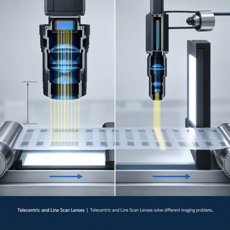
Telecentric and Line Scan Lenses for Precision Measurement Systems
10 min read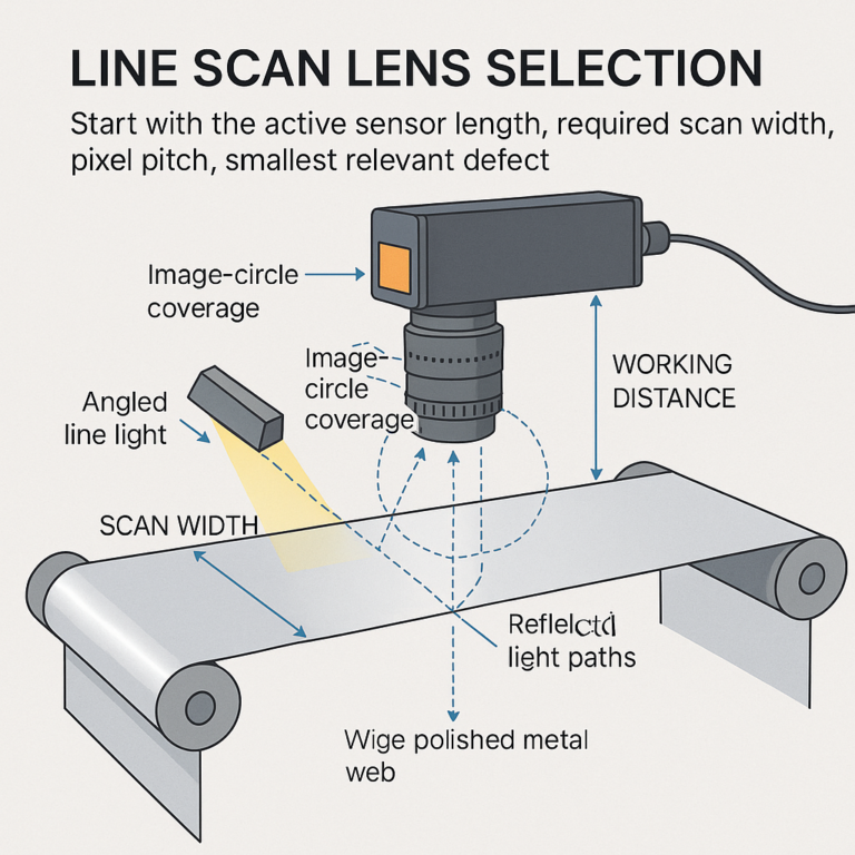
Line Scan Lens Selection for Large Sensors and Reflective Parts
10 min read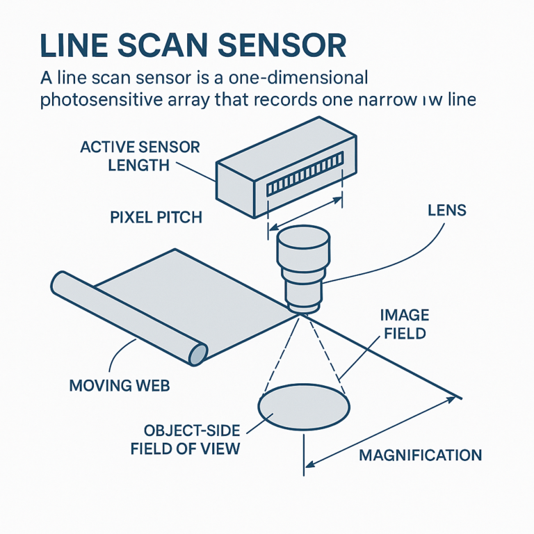
Line Scan Sensor Basics: Pixel Count, Pitch, and Lens Coverage
10 min readAbout SUPERIOR OPTICS
SUPERIOR OPTICS specializes in CCTV lenses, machine vision optics, and custom optical solutions for security, industrial imaging, and specialty applications. We also provide professional lens selection and application support.