


How to Choose and Test a Wide-Angle Lens for an Embedded Camera
A buyer-focused engineering workflow for selecting a wide-angle embedded camera lens, calculating initial coverage, checking sensor and mechanical compatibility, and converting prototype tests into a controlled purchase specification.
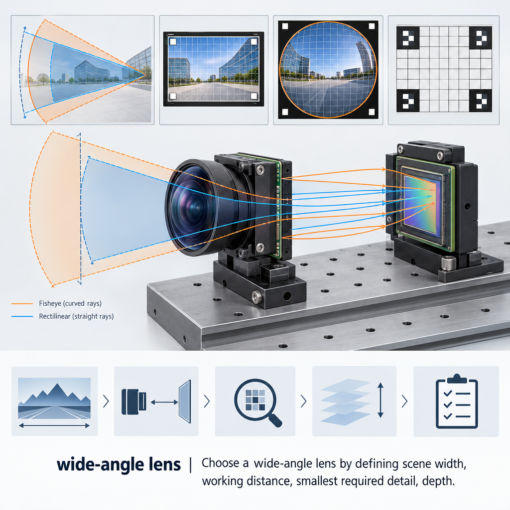
Key Takeaways
A defensible wide-angle lens decision starts with usable scene coverage and required detail, then tests the complete camera assembly rather than accepting focal length or sensor-resolution labels at face value.
- Select rectilinear or fisheye projection before comparing focal lengths because projection changes geometry, edge sampling and correction requirements.
- Calculate preliminary coverage from the sensor’s active dimensions, but verify the result on physical samples when distortion is substantial.
- Approve the lens and sensor as a system, including image circle, field-dependent sharpness, chief-ray-angle response, filter stack and clearance.
- Use controlled focus, distortion, shading, flare, spectral and environmental tests with recorded conditions and pass limits.
- Convert the approved prototype into a purchasing specification covering optics, mechanics, filters, locking, traceability and supplier change control.
The Short Answer
Choose a wide-angle lens by defining scene width, working distance, smallest required detail, depth range, illumination and allowable geometric error. Select rectilinear or fisheye projection, then estimate focal length from the sensor’s active area—not its nominal format label. Check image-circle coverage, field-dependent sharpness, optical-stack compatibility and mechanical clearance. Finally, test the assembled camera using RAW or minimally processed images for focus, distortion, shading, flare, spectral focus shift and sample variation. Treat calculations as screening tools; release the design only against measured acceptance criteria.
A lens can cover the full sensor yet still fail the application. Corners may be soft, color-shaded or mechanically obscured; correction may crop away needed coverage; focus may move after locking or with wavelength. Camera lens selection therefore has to connect an optical requirement to an assembled-camera acceptance test.
Start With the Embedded Camera Imaging Task
Record the target scene width and height, nearest and farthest object distances, smallest feature that must remain usable, lighting bands, motion and enclosure window. “See the whole doorway” is not an acceptance criterion. “Retain the required feature at the outer field after correction” can become one.
Separate three quantities:
- Optical field of view: the scene angle projected by the lens.
- Sensor coverage: the portion captured by the active pixel area without unacceptable cutoff.
- Usable field: what remains after calibration, dewarping, stabilization and crop.
This distinction affects purchasing. A quoted diagonal field of view cannot establish horizontal coverage, and an uncorrected view cannot establish the output dimensions after dewarping. The RFQ should identify the axis, active sensor mode, focus distance and whether the requirement applies before or after correction.
Choose the Right Wide-Angle Lens Projection
Rectilinear optics aim to keep straight scene lines straight, making them a practical starting point for measurement, barcode localization and interfaces where visible bending is unacceptable. As angle increases, objects near the edge can become stretched and receive fewer useful pixels for the target task.
Fisheye optics intentionally use a different mapping to place a very large angular scene on a finite sensor. They suit situational awareness and surround coverage when software can interpret or dewarp the image. For a deeper design comparison, see fisheye vs rectilinear lens and available fisheye lens options for wide-angle coverage.
| Decision factor | Rectilinear | Fisheye | Buyer consequence |
|---|---|---|---|
| Line rendering | Straight-line preservation is the design aim | Curved rendering is expected | Choose before calibration development |
| Edge behavior | Stretching can increase toward edges | Mapping depends on projection model | Test task detail by field position |
| Correction | May still need calibration | Dewarping is commonly required | Budget processing, latency and crop |
| Best fit | Inspection, localization, conventional video | Maximum awareness, surround views | Specify usable output, not raw angle alone |
Software correction can reduce geometric error, but it cannot recreate detail that the lens and sensor never resolved. Resampling also changes pixel density and may remove border regions. Judge corrected output with the production algorithm and output resolution.
A verified but limited background example from Michigan Technological University’s wide-angle converter documentation reports model-dependent barrel distortion and slight corner vignetting caused by a thick step-down ring. That page concerns legacy converter lenses, not embedded modules; its relevant lesson is only that optical design and surrounding hardware can create different edge failures.
Calculate Field of View for Embedded Cameras
Use active sensor width, height and diagonal for the selected readout mode. A nominal format name is not enough because cropping or a reduced-resolution mode can change the active area.
Engineering estimate for a rectilinear model:
FOV = 2 × arctan(sensor dimension ÷ (2 × focal length))
For an initial object-space estimate at working distance D:
scene dimension ≈ sensor dimension × D ÷ focal length
Rearranged:
focal length ≈ sensor dimension × D ÷ required scene dimension
These are geometric screening relationships, not supplier specifications. They omit distortion, focus-dependent behavior, tolerances and housing obstruction.
Illustrative calculation, not a product claim: assume a 6.4 mm active width, a 1,000 mm working distance and a required width of 2,000 mm. The first estimate is 6.4 × 1,000 ÷ 2,000 = 3.2 mm. Add application margin, obtain projection data and measure the real camera before fixing the focal length.
Fisheye calculations require the lens’s stated projection model or a calibrated angle-to-image-height relationship. Two lenses with the same focal length can therefore produce different coverage because sensor area, optical distortion and projection differ.
Match the Embedded Camera Lens to the Sensor
Coverage is necessary, but the image circle alone does not establish usable corners. Request performance by field position and at the intended aperture. The assembled test should include the actual sensor, cover glass, filters and holder.
| Parameter | What to verify | Failure symptom | Validation method |
|---|---|---|---|
| Active dimensions | Exact readout width and height | Wrong measured field | Inspect sensor mode and output |
| Image circle | Coverage with tolerance margin | Dark or cut corners | Uniform-field capture |
| Pixel pitch | Required spatial sampling | Detail plateaus below expectation | Target test by field |
| Lens response | Center, mid-field and corner performance | Sharp center, weak edges | Focus sweep and MTF proxy |
| Chief-ray response | Sensor and lens compatibility | Color or brightness shading | Flat-field RGB analysis |
| Optical stack | Filter and cover-glass configuration | Focus or corner degradation | Test production stack |
| Clearance | Rear barrel and sensor spacing | Contact or blocked focus travel | Drawing review and fit check |
Sensor Nyquist frequency is an engineering sampling relationship of 1 ÷ (2 × pixel pitch). It is a reference frequency, not proof that the assembled camera resolves that detail. Supplier MTF data should state field position, aperture, wavelength and focus condition; prototype testing then checks whether assembly tolerances preserve the expected result.
The principles behind lens sensor compatibility and image-circle coverage also apply when active-area dimensions and pixel pitch drive lens requirements, although line-scan and area-array integrations are not interchangeable.
Select Aperture, Focus Range, and Spectral Configuration
Treat F-number as a system variable. A smaller aperture may extend depth of field and reduce some aberrations, but it also reduces light and can make diffraction more influential. Compare candidate settings at the actual exposure time, illumination and motion level rather than choosing the highest F-number by default.
For finite working distances, focus using targets placed at the required near, nominal and far planes. Record the chosen barrel position before applying adhesive, then repeat the sweep after cure. An infinity-focused sample does not validate near-field logistics or inspection work.
Day/night cameras need separate visible and NIR checks with the intended filter mechanism and illuminator wavelength. Transmission and focus shift are lens-specific; do not infer them from an “IR compatible” label. SWIR uses different sensors and optical materials, so programs beyond silicon-visible/NIR imaging require a separate SWIR lens selection process for InGaAs inspection systems.
Verify Mechanical Fit for an Embedded Camera Lens
M12, C-mount, CS-mount and board-camera packaging describe interface families, not automatic interchangeability. For compact embedded camera lens options, compare supplier drawings for thread details, holder datum, barrel envelope, rear protrusion, focus travel and filter clearance.
Check the entire ray path. Holders, retaining rings, windows and seals can clip oblique rays even when the bare lens covers the sensor. Mechanical review should also define thread engagement, locking material, application process, cure conditions and permissible torque.
Shock, vibration and temperature requirements need program-specific tests. A practical failure criterion is measurable movement in focus, field coverage or distortion after exposure—not merely the absence of visible damage.
How to Test a Wide-Angle Lens Before Design Release
Use the production sensor mode and disable undocumented sharpening, geometric correction and noise reduction where possible. Record exposure, gain, aperture, target distance, illumination, temperature and software version so that samples and lots can be compared.
- Mechanical fit: inspect clearance, focus travel and edge obstruction.
- Through-focus sweep: capture center, mid-field and corners across repeatable focus increments.
- Sharpness: evaluate the smallest application-relevant feature in every required field region.
- Lens distortion testing: capture a calibrated grid, identify the model used and record residual error after calibration.
- Shading: use a uniform field to map brightness and color by position.
- Flare and ghosting: place representative bright sources inside and just outside the field.
- Repeatability: repeat after locking, environmental exposure and across multiple lenses, holders and camera assemblies.
Do not optimize focus only at the center. Field curvature can place the best corner focus at a different barrel position. The release position should satisfy the task-level threshold across all required regions, even if peak center sharpness is lower.
For day/night assemblies, repeat focus and sharpness checks in each operating band. For measurement or robot guidance, validate the full calibration pipeline and report residual error in application units as well as pixels.
Turn Camera Lens Selection Into a Production-Ready Specification
Replace “high resolution” and “low distortion” with measurable fields: active sensor mode, horizontal and vertical coverage, focus distance, aperture, wavelength, field positions, test chart, illumination, processing state and pass threshold.
The approved purchase specification should also include the lens and holder drawing revisions, filter stack, locking method, environmental sequence, sample size, lot traceability and incoming-inspection plan. Require notification before changes to glass, coatings, adhesives, barrel geometry or manufacturing location because apparently equivalent substitutions can alter assembled performance.
A second source is not qualified by matching focal length and mount. Run it through the same camera, processing and environmental tests. If its projection differs, existing calibration coefficients may no longer apply.
Apply the Selection Process to Common Embedded Camera Applications
- Security and door cameras: prioritize corrected coverage, faces or events at the field edge, backlight behavior and visible/NIR focus. The camera lens selection guide provides additional security-system context.
- Mobile robotics: specify calibration stability, overlap between cameras, motion exposure and the minimum navigational feature size by field position.
- Automotive surround view: treat projection, thermal movement, flare, sealing windows and calibration retention as module-level requirements.
- Barcode and near-field inspection: prioritize finite-distance focus, depth range, edge sampling and geometric residuals over headline diagonal angle.
These are engineering priorities, not universal pass limits. Each OEM must set thresholds from its own task and risk analysis.
Wide-Angle Lens Selection Checklist
Optical requirements
- Scene width and height at stated distances
- Required detail at center, mid-field and corners
- Rectilinear or documented fisheye projection
- Raw and corrected coverage requirements
- Aperture, illumination, exposure and spectral bands
Sensor and mechanical compatibility
- Active sensor dimensions, pixel pitch and readout mode
- Image circle, corner response and optical stack
- Thread, holder datum, rear clearance and focus travel
- Window, filter and enclosure obstruction review
- Locking process and environmental constraints
Prototype and incoming inspection
- Recorded focus sweep and field-dependent sharpness
- Distortion model, calibration version and residual
- Uniform-field brightness and color maps
- Flare, ghosting and multispectral focus checks
- Sample, assembly and lot repeatability rules
For a technical review, submit the sensor part number and active mode, required coverage, working-distance range, wavelength, aperture constraints, mechanical envelope and expected annual volume. Those inputs allow a lens recommendation or custom optical assessment to start from testable conditions rather than a focal-length guess.
Frequently Asked Questions
What focal length is considered wide angle for an embedded camera?
No universal focal-length boundary applies. Whether a lens is wide depends on active sensor dimensions, projection and required scene coverage. Define horizontal and vertical field of view first, then estimate focal length using the active area. Verify the result with supplier projection data and an assembled-camera measurement.
Can two wide-angle lenses with the same focal length produce different fields of view?
Yes. Different active sensor areas, projection models, distortion profiles and usable image circles can produce different measured fields from the same nominal focal length. Suppliers may also quote horizontal, vertical or diagonal angles under different conditions. Compare the stated axis, sensor mode, focus distance and correction state.
Does software distortion correction improve lens sharpness?
No, not inherently. Calibration and dewarping can make geometry more useful, but they resample existing image data and may crop borders. They cannot recover detail that was not resolved optically or sampled by the sensor. Evaluate sharpness and task performance on the corrected production output, especially near edges.
Should an M12 lens be used for a high-resolution embedded camera?
It can be, provided the specific lens, holder and sensor pass the required assembled-camera tests. The mount name does not establish image quality. Review field-dependent optical performance, pixel pitch, image circle, optical stack, focus stability and tolerances. Avoid approving a lens solely from megapixel or video-format labels.
What should an OEM include in a wide-angle lens RFQ?
Include sensor part number, active dimensions and mode; required horizontal and vertical coverage; working and focus distances; aperture; wavelength and filter stack; mechanical envelope; projection preference; image-quality and distortion thresholds; environmental conditions; locking method; sample plan; traceability; and material, coating or process change-notification requirements.
Topics
Related Articles
Complete Guide for CCTV Camera Wide Angle and Other Security Lenses
6 min read
CCTV Camera Wide Angle Lens – Get More Coverage with a Single Camera
5 min readAbout SUPERIOR OPTICS
SUPERIOR OPTICS specializes in CCTV lenses, machine vision optics, and custom optical solutions for security, industrial imaging, and specialty applications. We also provide professional lens selection and application support.