


How to Select a Machine Vision Lens Selection: FOV & Working Distance
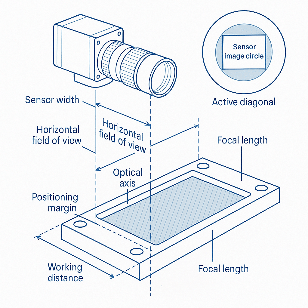
Define coverage and installation constraints, calculate magnification and object-space sampling, then validate a focal-length estimate against the actual lens and task.
Key Takeaways
Machine vision lens selection works best as a sequence: define coverage, check sampling, estimate magnification and focal length, then validate the lens in the actual installation.
- Specify horizontal and vertical coverage, including positioning uncertainty and the features that must remain visible.
- Use active sensor dimensions and output pixel count to calculate magnification and object-space sampling.
- Treat a focal-length estimate based on working distance as a shortlist tool, not a mechanical installation dimension.
- Check image circle, focus range, distortion, depth of field and physical clearance before selecting a catalog model.
- Approve the camera, lens, lighting and processing together with a task-specific sample test.
The Short Answer
Machine vision lens selection starts by defining the required field of view and installation distance, then matching them to the camera’s active sensor dimensions. Calculate magnification as sensor width divided by horizontal field of view. Estimate focal length only to narrow the options; confirm the actual lens’s field, focus range and working-distance reference from its documentation. Check feature sampling, edge quality, distortion, object-height variation and mechanical clearance. Finally, test the intended camera and illumination on representative objects, because a correct coverage calculation alone does not prove inspection reliability or measurement accuracy.
Define What Must Fit Inside the Image
Begin with the inspection drawing rather than a preferred focal length. Record the whole area that must remain visible, including locating features, orientation changes and position uncertainty. Specify horizontal and vertical dimensions at a named object plane. For moving products, include the positions at which the image may actually be captured.
Field of view describes the object area seen by the imaging system. Working distance describes the separation between an agreed lens reference and that object plane. Edmund Optics’ imaging fundamentals also separates these from sensor size, pixel size and magnification. Keep those inputs distinct in the RFQ.
| Selection input | Record this | Example only |
|---|---|---|
| Required coverage | Width, height and positioning allowance | 180 × 135 mm at the inspection plane |
| Camera active area | Width and height in mm | 12.8 × 9.6 mm |
| Output sampling grid | Active pixels used by the algorithm | 4096 × 3072 pixels |
| Installation envelope | Available lens-front-to-object distance and reference | Approximately 400 mm, with adjustment space |
| Smallest important feature | Dimension, contrast and location | A 0.20 mm mark near the field edge |
| Object variation | Height range, tilt and movement | To be measured from the real fixture |
| Illumination | Spectrum, geometry and permitted exposure | To be agreed for the production task |
All example dimensions in this guide are hypothetical. They illustrate the calculation sequence and are not a guaranteed configuration or SUPERIOR product specification.
Check the Camera Aspect Ratio
Required coverage must fit in both directions. A 4:3 active sensor used at one magnification produces a corresponding rectangular field for ordinary, low-distortion imaging. If the object and sensor aspect ratios differ, one dimension will normally include additional scene area, or the output will need cropping.
For the example, 180:135 and 12.8:9.6 are both 4:3. A horizontal calculation therefore produces the required vertical coverage as well. If a later camera mode crops the image to a different ratio, repeat the calculation using its actual active area and retained pixels.
Do not assume that resizing an output image gives the same result as capturing more optical detail. State whether the algorithm uses raw pixels, binned pixels, a cropped region or a scaled image.
Calculate Magnification and Object-Space Sampling
Use physical sensor dimensions for magnification and pixel count for object-space sampling:
Magnification m = sensor width / horizontal FOV
Object-space sampling = horizontal FOV / horizontal pixel count
The same relationships apply vertically when the dimensions are paired consistently. For the illustrative camera:
| Calculation | Result | Interpretation |
|---|---|---|
| 12.8 mm / 180 mm | 0.0711× magnification | The object field is reduced onto the sensor |
| 9.6 mm / 0.0711 | 135 mm vertical field | Confirms coverage in the second direction |
| 180 mm / 4096 pixels | 0.04395 mm per pixel | Approximately 43.95 micrometers per pixel in object space |
| 0.20 mm / 0.04395 mm per pixel | Approximately 4.55 pixels | Nominal feature sampling, not proof of detection or measurement accuracy |
Whether 4.55 pixels is sufficient depends on the task, contrast, blur, motion, lighting and algorithm. Establish the required pixel coverage through the application’s validation method. Avoid declaring a universal pixels-per-defect rule or treating a subpixel algorithm claim as a complete system accuracy specification.
Edmund Optics’ resolution note connects sensor sampling and magnification. The calculations above are original worked examples using those relationships, with their assumptions stated explicitly.
Estimate Focal Length, Then Check the Actual Lens
A commonly used first-pass approximation for conventional imaging is:
f ≈ sensor width × working distance / horizontal FOV
Using 12.8 mm, 400 mm and 180 mm gives an estimate of about 28.4 mm. This is a starting point for comparing available lenses. It is not a promise that a nominal 28 mm lens will produce the exact field at a mechanically measured 400 mm.
The approximation depends on simplified geometry. Entrance-pupil and principal-plane locations, focusing behavior and distortion can matter. In its focal-length and field-of-view guide, Edmund Optics explicitly cautions against treating these estimates as final mechanical design values.
For shortlisted models, obtain field-of-view data or a lens-specific calculation at the intended distance. Verify the supplier’s working-distance reference, minimum focus distance, focus travel and tolerances. Keep adjustment allowance in the installation instead of freezing the machine drawing around the approximate value.
Check Practical Constraints Before Choosing a Model
| Constraint | What to verify | Why the first-pass calculation is insufficient |
|---|---|---|
| Sensor coverage | Usable image circle and edge performance | The calculated focal length says nothing about supported sensor area |
| Detail | MTF at useful frequencies and field locations | Pixel coverage alone does not describe optical contrast |
| Working distance | Reference surface, permitted range and focus setting | A calculator’s distance may not match the supplier drawing |
| Depth of field | Near and far object positions without refocusing | A focused center-plane sample does not validate height variation |
| Geometry | Distortion, calibration and perspective sensitivity | Coverage does not establish measurement accuracy |
| Mechanical fit | Lens envelope, rear clearance, adapter and focus lock | A compatible mount name does not prove a usable assembly |
| Production conditions | Light, exposure, vibration and thermal state | A static bench sample may not represent the inspection process |
The lens specifications guide provides the next step for reading MTF, aperture and distortion evidence under comparable conditions.
Decide Whether Conventional or Telecentric Optics Fit the Task
Use conventional fixed-focal-length optics when their coverage, image quality and perspective behavior meet the inspection requirement. Consider telecentric optics when apparent size changes with object distance are important to dimensional measurement. Confirm the actual magnification, working distance, sensor coverage and specified telecentric performance of the proposed model. Edmund Optics describes the underlying perspective distinction in The Advantages of Telecentricity.
| Task | Sensible starting route | Additional check |
|---|---|---|
| Presence, print or surface inspection at controlled height | Conventional machine vision lens | Field detail, lighting and object-height tolerance |
| Dimensional measurement with relevant height variation | Telecentric lens evaluation | Telecentricity, calibration, distortion and usable depth range |
| Close-up of a small area | Macro or suitable finite-conjugate optics | Required magnification and physical access |
| Continuous material inspection with a line camera | Line-scan optical design review | Active line length, motion sampling and illumination |
These are engineering screening routes, not a guarantee that a lens family solves the application. Review the machine vision lens portfolio and telecentric lens options only after defining the task and camera.
Run a Coverage-to-Acceptance Trial
Use representative objects at the permitted positions and heights. Keep camera processing documented; sharpening, resizing and automatic exposure can conceal what changed between trials. Capture center and corner features, then repeat the near and far object conditions without silently refocusing.
Record the actual field dimensions and measured installation distance, the focus-lock state, aperture, light settings, exposure, gain and processing. Identify the characteristic that determines acceptance: readable characters, defect detection, edge position or dimensional repeatability. Compare against the application limit rather than the visual impression of a sharp photograph.
For procurement, separate three outcomes: the lens fits; the image covers the required area; and the complete system passes the task. Only the last outcome supports the final application approval.
Request a Lens Review With the Geometry Attached
Send the camera or sensor datasheet, required horizontal and vertical coverage, working-distance envelope, object-height range and smallest relevant feature. Include a machine sketch showing obstructions and lighting access. Discuss your machine vision lens selection with SUPERIOR using those inputs so candidate models can be reviewed against a defined installation.
Frequently Asked Questions
Can focal length be selected from working distance alone?
No. The required field of view and physical sensor dimensions are also needed for an initial estimate. Even then, a simplified formula only narrows the candidate range. Confirm the actual lens’s field data, focus capability, distance reference and installation clearances before finalizing the mechanical layout or ordering production quantities.
Does a smaller field of view always improve inspection?
A smaller field puts more pixels across a given object feature when the same pixel grid is used, but it can exclude required coverage or positioning allowance. Optical contrast, lighting, motion and processing still affect the result. Improve sampling only after confirming that the whole inspection area remains visible.
What is the difference between pixel size and object-space sampling?
Pixel size is a physical dimension at the sensor. Object-space sampling describes how much of the inspected scene maps onto one retained pixel. It depends on magnification and can be estimated from field of view divided by pixel count. Neither quantity alone establishes defect-detection reliability or dimensional measurement accuracy.
Should I choose a telecentric lens for every measurement task?
Not automatically. Evaluate how object-height variation, perspective, distortion and calibration affect the required result. Telecentric optics can reduce sensitivity of apparent size to distance within their specified operating range, but their magnification, working distance, coverage and other constraints must fit the application. Validate the assembled measurement system against its actual error budget.
Why does a calculator’s focal length differ from a sample test?
First-pass calculators simplify lens geometry and may use a different distance reference from the mechanical installation. Actual entrance-pupil position, focusing behavior, focal-length variation and distortion can affect the field. Check the lens-specific drawing and field data, then measure the assembled setup rather than forcing the result to match an approximate calculation.
Related Articles
How to Qualify and Compare Machine Vision Lens Suppliers for OEMs
11 min read
Machine Vision Lens RFQ Checklist for OEM Production Programs
11 min read
Large-Sensor Machine Vision Lenses: Image Circle and Edge Quality
12 min readAbout SUPERIOR OPTICS
SUPERIOR OPTICS specializes in CCTV lenses, machine vision optics, and custom optical solutions for security, industrial imaging, and specialty applications. We also provide professional lens selection and application support.