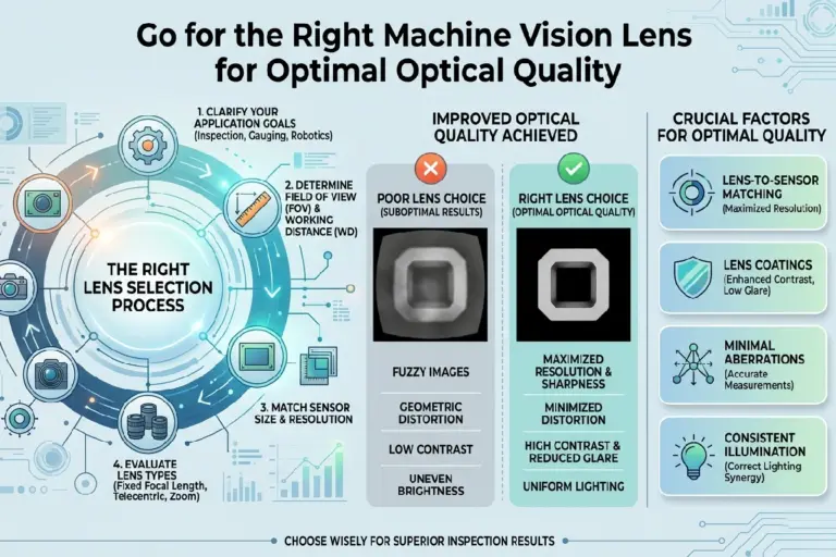
Machine Vision Lens MTF: Match Resolution to Camera Pixel Size
Machine Vision Lens MTF describes how well a lens preserves contrast at specified spatial frequencies on the image sensor. Matching a lens to a camera starts with pixel pitch, but it does not end there. The lens must provide adequate contrast at the frequencies the inspection uses—and at the intended aperture, wavelength, magnification, working distance, and field position.
This approach is more useful than selecting a “megapixel lens.” Megapixel labels do not define pixel size, retained contrast, sensor coverage, or operating conditions.
Key Takeaways
- Calculate sensor Nyquist frequency as 1 ÷ (2 × pixel pitch in millimeters).
- Use Nyquist as a theoretical sampling boundary, not as proof of inspection performance.
- Set the MTF requirement at the spatial frequencies associated with the relevant defect, edge, or measurement feature.
- Compare lens data at the actual aperture, wavelength, magnification, focus distance, and field position.
- Account for the combined performance of the lens, sensor, illumination, mechanics, and image-processing chain.
- Treat megapixel ratings as product-family labels, not substitutes for MTF and image-circle data.
What Is Machine Vision Lens MTF?
MTF measures contrast transfer by spatial frequency
Modulation transfer function, or MTF, expresses the contrast retained by an imaging component as spatial frequency increases. Lens specifications commonly report image-space frequency in line pairs per millimeter, or lp/mm.
Broad light and dark regions represent low spatial frequencies. Finer alternating regions represent higher frequencies. A lens can reproduce the broad pattern with strong contrast while reducing the contrast of fine detail. The MTF curve shows that change.
An MTF value of 1 represents complete contrast transfer under the stated model; 0 means that no modulation remains. Actual results fall between those limits and depend on the test conditions. The Opto Engineering guide to matching lens and sensor MTF explains that lens and sensor MTF values can be multiplied as an estimate of total system MTF. That estimate is useful for comparison, although a production system can also be limited by focus error, motion, noise, illumination, and processing.
Why MTF is more useful than a megapixel rating
A megapixel rating omits several details needed for optical selection: pixel pitch, sensor dimensions, aperture, wavelength, magnification, field position, and retained contrast. Sensors with the same pixel count may have different pixel pitches. Cameras with different pixel counts may use the same pitch but require different image-circle diameters.
A statement such as “MTF 0.3 at 100 lp/mm” is more specific than “five-megapixel lens,” but only when its test conditions are known. Aperture, wavelength, field point, magnification, and measurement method can materially change the result. Guidance on megapixel machine-vision lens misconceptions similarly emphasizes pixel pitch and comparable test conditions rather than megapixel count alone.
Read center, edge, sagittal, and meridional data separately
On-axis curves describe performance near the center of the image. Off-axis curves cover intermediate field positions and the edge or corner, where aberrations often have a greater effect.
Sagittal and meridional curves describe contrast transfer for detail in different orientations relative to the optical field. Separation between them indicates directional differences in image quality. For procurement, identify the field location and orientation of the feature that matters. The best center-field curve may not represent a defect near a corner or an edge running in the less favorable direction.
Start With Camera Pixel Size and Sensor Nyquist Frequency
Calculate Nyquist frequency from pixel pitch
For a regularly sampled sensor with pixel pitch p in millimeters, the one-dimensional Nyquist frequency is:
Sensor Nyquist frequency = 1 ÷ (2p)
When pitch is given in micrometers:
Sensor Nyquist frequency in lp/mm = 500 ÷ pixel pitch in µm
For 5 µm pixels:
500 ÷ 5 = 100 lp/mm
For 3.45 µm pixels:
500 ÷ 3.45 = 144.9 lp/mm
Nyquist is the theoretical upper sampling boundary for a one-dimensional periodic signal. It does not guarantee that the lens and sensor will deliver enough contrast at that frequency, nor does it prevent aliasing when scene content exceeds the boundary.
Distinguish sampling density from usable resolution
At Nyquist, a periodic line-pair pattern has a two-pixel-pitch period. Actual sampled contrast depends on the pattern’s phase relative to the pixel grid, the sensor’s pixel aperture, and the rest of the imaging chain. Color-filter arrays and demosaicing can introduce additional directional and spectral effects.
For that reason, the Nyquist calculation is best used to screen candidate lenses and establish the relevant frequency range. It is not a complete image-quality specification.
Set the requirement at the frequency the inspection uses
A presence check for a large part may rely mainly on low-frequency contrast. A narrow scratch, small code element, or tightly localized edge can place more weight on higher frequencies. These tasks should not be assigned the same MTF target simply because they use the same camera.
Start with Nyquist, then determine the frequency content associated with the smallest feature that must be detected or measured. Specify the minimum acceptable contrast there, with margin for production variation.
How to Match Lens Resolution to Camera Pixel Size
Connect camera sampling to the inspection task
A practical answer to how to match lens resolution to camera pixel size requires four inputs:
- Pixel pitch and sensor Nyquist frequency.
- Field of view and object-space pixel size.
- The size, orientation, and location of the relevant feature.
- The minimum system contrast required by the vision algorithm.
Features represented by only a few pixels are particularly sensitive to blur, focus drift, motion, sampling phase, and weak contrast. More pixels across the feature usually provide more margin, but pixel count alone does not establish measurement accuracy or detection reliability.
Define a contrast requirement, not just a resolution number
There is no universal MTF threshold for machine vision. An acceptable value depends on feature contrast, illumination, sensor noise, exposure, processing, and the cost of false accepts or false rejects.
A useful procurement specification states the minimum MTF at one or more image-space frequencies and field positions. For example, it may set limits for the center, mid-field, and corner at the intended aperture and wavelength. Validate the numerical limits with representative parts and the production algorithm rather than adopting an arbitrary threshold.
Compare candidate lenses under matching conditions
When evaluating machine vision lenses for industrial inspection, align the following conditions before ranking products:
- Spatial-frequency units and image-space or object-space reference.
- Working aperture or f-number.
- Illumination wavelength or spectral band.
- Magnification and working distance.
- Focus distance or conjugate.
- Field position and sagittal or meridional orientation.
- Sensor format and required image circle.
A center-field curve measured at one aperture cannot establish corner performance at another. If suppliers publish data under different conditions, request comparable data or test the lenses in the application.
Do not specify an industrial camera lens by megapixels alone
Megapixel labels can help narrow a product search, but they do not establish usable contrast. A buyer-ready lens specification includes pixel pitch, sensor dimensions, target frequencies, minimum MTF, active field points, spectral conditions, aperture, working distance, and magnification.
Translate Sensor Resolution Into Object-Space Resolution
Relate magnification to field of view
Approximate lateral magnification is:
Magnification = image size ÷ object size
If a 12 mm-wide sensor images a 120 mm horizontal field, the magnification is approximately 0.1×. A 1 mm object-space feature then produces an image about 0.1 mm wide on the sensor.
Spatial periods scale by magnification. Accordingly, an image-space MTF chart and an object-space feature requirement must be converted to the same reference space before comparison.
Calculate object-space pixel size
For a rectilinear setup, an initial estimate is:
Object-space pixel size = field of view ÷ number of pixels across that field
A 120 mm field sampled by 4,000 horizontal pixels gives:
120 mm ÷ 4,000 = 0.03 mm per pixel, or 30 µm per pixel in object space.
This figure describes sampling density. It is not guaranteed resolving power. Optical blur, sensor MTF, noise, feature contrast, motion, and processing can make effective resolution coarser.
Define the feature before selecting the lens
For periodic detail, the Nyquist criterion requires at least two samples per cycle. An isolated defect or edge is not fully described by that rule, and two-pixel representation often leaves little production margin. Stable localization, classification, and dimensional measurement may require more samples across the feature.
Record the feature’s width, orientation, inherent contrast, permissible location, and required measurement uncertainty. Then verify performance with the complete imaging system.
Evaluate Lens MTF Under the Actual Imaging Conditions
Field position and sensor coverage
If the inspection uses the full frame, review MTF at the center, representative mid-field positions, and the limiting edge or corner. If only part of the sensor is active, define that region so the specification reflects the actual requirement.
The image circle must also cover the sensor diagonal. Inadequate coverage can cause vignetting or unusable edge regions, as noted in this machine-vision lens selection overview.
Aperture
Stopping down can reduce some aberrations and increase depth of field. It also increases diffraction and reduces the light reaching the sensor. Resolution therefore does not improve indefinitely as the aperture becomes smaller.
Choose the operating f-number after considering object depth, exposure time, lighting power, motion, sensor noise, and diffraction. Compare MTF at that f-number rather than at whichever aperture produces the most favorable catalog curve.
Wavelength
Focus and aberration correction vary with wavelength, so broadband visible-light data may not predict performance under a narrow red LED, near-infrared source, or ultraviolet illumination.
For a wavelength-specific system, check transmission, coatings, focus shift, and MTF in the operating band. Applications outside the visible spectrum may require infrared camera lenses for wavelength-specific imaging or another design corrected for the required wavelengths.
Working distance and magnification
Lens performance can change with conjugate. A lens characterized at infinity may behave differently at close focus, particularly if it was not optimized for the intended magnification.
Request MTF data at the planned working distance and magnification when available. If the published curves do not represent the installation, include application-level testing in the qualification plan.
Use an MTF Comparison Table to Screen Candidate Lenses
Record the camera and application requirements before reviewing catalog curves. The table below keeps the requirement, evidence, and acceptance question separate.
Machine Vision Lens MTF Comparison Checklist
| Selection input | How to determine it | Lens data to compare | Acceptance question | Common risk if ignored |
|---|---|---|---|---|
| Camera pixel size / pixel pitch | Camera sensor specification | Supported frequency range in lp/mm | Does the data reach the relevant camera frequencies? | Megapixel label masks an optical mismatch |
| Sensor Nyquist frequency | 500 ÷ pixel pitch in µm | MTF at or below calculated Nyquist | Is contrast sufficient at the application frequency? | Nyquist is mistaken for guaranteed resolution |
| Required object-space resolution | Smallest defect or measurement feature | Object-space or converted image-space MTF | Can the system represent the feature with margin? | Pixel sampling is confused with detection capability |
| Target image-space spatial frequency | Convert feature period using magnification | MTF at the same lp/mm reference | Are units and reference spaces consistent? | Object- and image-space values are mixed |
| Minimum acceptable MTF contrast | Validate with algorithm and representative parts | MTF value at target frequencies | Does contrast meet the validated threshold? | “Resolution” is specified without contrast |
| Field position | Define active inspection region | Center, mid-field and corner curves | Does every required region pass? | Center data is applied to the full sensor |
| Working aperture | Set from depth, exposure and diffraction tradeoffs | MTF at the same f-number | Was the lens characterized at the operating aperture? | Unlike conditions are compared |
| Illumination wavelength | Source spectrum and sensor response | Monochromatic or polychromatic MTF | Does the test band match the application? | Focus and contrast change with wavelength |
| Working distance and magnification | Mechanical layout and field of view | MTF at the stated conjugates | Does published data represent the installation? | Infinity data is used for close focus |
| Lens-to-sensor format coverage | Sensor width, height and diagonal | Image circle and off-axis performance | Is the full active sensor usable? | Vignetting or weak corner performance |
Normalize the data before ranking lenses
Do not directly rank a monochromatic f/4 curve against a broadband f/8 curve without additional evidence. First reconcile units, aperture, wavelength, conjugate, field position, and measurement method.
Know when catalog data is insufficient
Application testing is warranted when the relevant feature is close to the sampling limit, dimensional tolerances are tight, edge performance controls acceptance, illumination falls outside the normal visible range, or published curves omit the required working geometry. Test with production lighting, representative parts, actual camera settings, and the intended algorithm.
Common Machine Vision Lens MTF Selection Errors
Comparing unlike MTF curves
A higher curve may reflect a more favorable aperture, wavelength, field point, or conjugate rather than a better lens for the installation. Ask each supplier to disclose the measurement conditions.
Applying center performance to the full sensor
Center-field MTF does not predict corner performance. The distinction matters when defects may appear anywhere in the frame or when a measurement spans a large part of the image.
Treating aperture as an optics-only decision
Aperture affects aberrations, diffraction, depth of field, exposure, and motion blur. Select it as part of the complete imaging design, including lighting, sensor sensitivity, cycle time, and mechanical tolerance.
Treating pixel count as proof of capability
Additional pixels increase sampling density only. They do not guarantee that the system preserves enough contrast to detect a defect or meet a dimensional tolerance.
When to Use a Standard Lens, Telecentric Lens, or Custom Optical Assembly
Standard machine-vision lenses
A standard lens is a reasonable choice when perspective is acceptable, object depth is controlled, the image circle covers the sensor, and measured or specified MTF meets the field-wide requirement at the operating conditions.
Telecentric optics
Consider telecentric lenses for dimensional metrology when reduced perspective sensitivity and stable apparent size over a specified object-position range are important. Telecentricity does not eliminate the need to check MTF, distortion, depth of field, wavelength, and sensor coverage.
Custom optical assemblies
A custom assembly may be justified when no catalog lens provides the required combination of format, field of view, working distance, aperture, spectral band, distortion, and field-wide MTF. The decision should also account for qualification effort, integration risk, production volume, and lifecycle availability.
SUPERIOR can review camera pixel pitch, sensor format, field of view, working distance, wavelength, aperture target, and required object-space resolution. Submit those inputs for custom optical design for application-specific MTF targets or lens-selection support.
Frequently Asked Questions
Can a lens with lower MTF than the sensor Nyquist frequency still be suitable for machine vision?
Yes. A lens can be suitable even if its contrast is low near sensor Nyquist, provided the inspection depends on lower spatial frequencies and the complete system preserves enough contrast for reliable detection or measurement. Suitability should be validated at the feature frequency, operating conditions, field position, and required algorithm margin.
Should MTF be evaluated at Nyquist frequency or at the spatial frequency of the inspected feature?
Evaluate both, but make the inspected feature’s spatial frequency the primary application target. Nyquist defines the sensor’s theoretical sampling boundary; it doesn’t define the contrast required by every task. Reviewing MTF near Nyquist still reveals available headroom and helps assess vulnerability to fine-detail loss, aliasing, and future requirement changes.
Why can two lenses marketed for the same sensor format produce different inspection results?
Sensor-format compatibility establishes coverage, not equal image quality. Two lenses may differ in field-wide MTF, aberration correction, distortion, wavelength response, aperture behavior, focus stability and manufacturing tolerance. Those differences can change edge contrast and measurement repeatability even when both lenses cover the same sensor and carry similar megapixel labels.
Does stopping down always improve machine vision lens resolution?
No. Stopping down can reduce some aberrations and increase depth of field, but smaller apertures also increase diffraction and reduce available light. The best f-number is an application-specific balance among MTF, object depth, exposure, motion, illumination power, sensor noise and the field positions that must meet the inspection requirement.
How should I evaluate lens MTF for a line-scan camera?
Calculate Nyquist from the line-scan sensor’s pixel pitch, then assess MTF in the scan and cross-scan directions at the required field positions. Include web motion, encoder accuracy, line rate, illumination geometry and lens magnification. For wide sensors, edge performance and image-circle coverage can be as important as center resolution.
See line scan lenses for high-resolution inspection when screening optics for continuous-web or moving-part systems.
When should an OEM request measured MTF data instead of relying on a lens datasheet?
Request measured data when published curves omit the intended aperture, wavelength, field position, magnification or working distance, or when the inspection operates close to its contrast and sampling limits. Measurements are also appropriate for qualification programs that need lot controls, acceptance limits or traceable evidence that production optics meet application-specific requirements.
Related Articles
How to Select a Machine Vision Lens by FOV, Sensor, and Distance
1 min read
Primary Reasons for the Growing Popularity of Machine Vision Lenses
1 min read