SWIR Lens Spectral Matching: Sensor, Lighting, and Coatings
A buyer-focused method for matching an InGaAs sensor, illumination source, lens glass, anti-reflection coating, filters, and protective windows as one SWIR optical stack.
Key Takeaways
A mechanically compatible SWIR lens is not necessarily spectrally compatible; buyers should compare every optical component across the inspection system’s actual operating wavelengths.
- Define the operating band from target contrast and illumination rather than relying on a broad SWIR label.
- Compare source output with the sensor’s wavelength-dependent sensitivity, including any cover glass and sensor-side filter.
- Request assembled-lens transmission and coating data because focal length and aperture do not reveal spectral throughput.
- Treat enclosure windows, filters, and process barriers as parts of the optical budget.
- Validate throughput, focus, contrast, field coverage, and mechanics together on the intended sensor and lighting stack.
SWIR Lens Spectral Matching is a wavelength-overlap problem, not a mount-selection exercise. A lens can fit the camera, cover the sensor and provide the required field of view yet still reduce signal or contrast because its glass, coatings or surrounding windows do not support the active band.
The practical test is simple: does every component perform adequately at the wavelengths that reveal the target feature? That question should be answered with spectral curves and system-level images, not a generic “SWIR compatible” description.
Start With the Actual SWIR Operating Band
Define the inspection target, material response, and required contrast
Begin with the feature that must be separated: moisture from dry material, coating from substrate, or one material class from another. SWIR usually forms images from reflected radiation, and materials can reflect or absorb SWIR differently from visible light. Water-rich regions, for example, may appear darker because water absorbs SWIR effectively, according to Schneider-Kreuznach’s machine-vision guidance.
The required band should therefore follow measured or documented target response. If the target has little contrast at the selected wavelength, a higher-transmission lens cannot create it.
Set the usable wavelength range instead of specifying a nominal SWIR band
“SWIR” is not a sufficiently precise purchasing specification. Schneider-Kreuznach describes 900–1700 nm as a common industrial machine-vision range while also noting that classification boundaries vary. Record a lower wavelength, upper wavelength and any narrower high-priority interval.
A system operating around one illumination line has different optical requirements from one expected to image continuously across a broad VIS-SWIR range.
Identify broadband, narrowband, or multispectral illumination
For broadband lighting, compare performance across the complete source spectrum after filters. For narrowband lighting, inspect the source’s center wavelength and spectral width rather than assuming a single ideal wavelength. Multispectral systems need acceptable transmission and focus at every channel, including the gaps between coating bands where performance may fall.
Map InGaAs Sensor Sensitivity Against SWIR Illumination Wavelength
Read the InGaAs sensor sensitivity curve
Use the model-specific sensitivity or quantum-efficiency curve. Endpoint values alone conceal variation inside the range. Extended-SWIR and VIS-SWIR devices can also have materially different limits; Schneider-Kreuznach reports that sensor sensitivity ranges depend on model and identifies some VIS-SWIR sensors operating from 400 to 1700 nm.
Compare source output and irradiance at the target
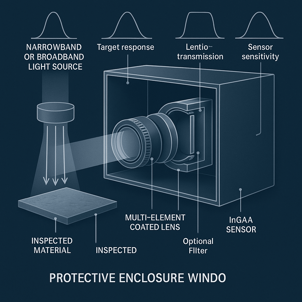
Overlay three curves on one wavelength axis: source output, target reflectance or absorption, and sensor response. Then add the optical components. The useful signal exists only where these functions overlap. Also confirm that the quoted source output reaches the target after distance, geometry, diffuser, filter and enclosure losses.
Include the sensor-side optical stack
Request details for the camera’s cover glass, microlenses and installed filters. Two cameras using related InGaAs arrays may produce different system responses if their sensor-side stacks differ. This is an engineering inference to verify with camera documentation or measurement, not a substitute for the manufacturer’s spectral curve.
Verify Optical Glass Transmission Through the Full Lens Path
Evaluate every lens element
Ask for assembled-lens transmission over the required band. A catalog statement about substrate transmission does not include all elements, cemented groups, coatings or internal reflections. Common glass may transmit some SWIR, but that does not mean a visible-optimized lens will deliver suitable SWIR image quality, as summarized in this SWIR lens selection guide.
Buyers comparing Infrared Camera Lenses for SWIR imaging-path evaluation should request the wavelength interval, test conditions and whether the curve represents a sample, a design estimate or guaranteed production limits.
Check band edges and focus
Transmission can weaken near a material or coating boundary. Focus can also move with wavelength because different wavelengths have different best-focus planes. A lens that looks sharp under one narrowband source may not remain sharp under broadband or switched-channel illumination.
Avoid visible-optimized assumptions
Focal length, f-number and mount specify geometry, not spectral correction. Confirm transmission, chromatic focal behavior, sensor coverage and resolution at the working wavelength. Smaller pixels place greater demands on lens performance, so pixel pitch belongs in the optical request.
Specify Anti-Reflection Coatings for the Required SWIR Band
Match coating coverage to the active overlap
Anti-reflection coatings for SWIR lenses should be evaluated where illumination, target response and InGaAs sensor sensitivity overlap. Request a reflectance or transmission curve with angle and environmental conditions where relevant. A broad coating label without a defined band is not enough.
Compare broadband and narrowband options
A narrowband coating may prioritize performance around a selected illumination band. A broadband coating can support multiple channels but must be assessed across the entire interval. Neither is automatically better: the decision depends on bandwidth, incidence angles, production tolerances and whether the source wavelength may change.
Consider cumulative reflection and ghosting
Every air-to-glass surface can contribute reflection. In a multi-element lens, small losses can accumulate and reflected paths may form ghosts or lower contrast. Review coating performance as part of the assembled optical system, especially when bright highlights or high-dynamic-range scenes are expected. Additional background is available in lens knowledge for optical glass transmission and coating selection.
Evaluate SWIR Protective Window Materials Before Finalizing the Lens
Compare spectral and environmental requirements
A window that appears clear to the eye may not provide adequate SWIR transmission. Obtain material and coated-window curves across the operating band, then balance them against impact, abrasion, sealing, temperature and chemical-exposure requirements. Visual clarity is not evidence of SWIR compatibility.
Assess coatings, thickness and surface quality
Specify coating band, clear aperture, thickness, wedge, flatness and surface quality where image performance demands them. A tilted or wedged window may be useful for managing reflected paths, but it can also alter packaging and image geometry. The appropriate limits depend on aperture, field angle and working distance.
Include every barrier in the throughput budget
Count the camera cover, housing window, filter, process barrier and protective shield. As an illustrative calculation—not product data—components transmitting 85%, 90% and 92% at one wavelength produce about 70% combined throughput: 0.85 × 0.90 × 0.92. Adding an 88% filter reduces it to about 62% before sensor response is considered.
Use a Compatibility Matrix to Match Sensor, Light, Lens, Coating, and Window
To complete SWIR Lens Spectral Matching, compare every component across the same required wavelength range. Compatibility means that usable spectral performance overlaps the operating band without unacceptable throughput, focus or contrast loss.
| Optical Stack Component | Specification to Collect | Wavelength Range or Spectral Curve to Review | Compatibility Check | Potential Mismatch Risk | Selection Decision |
|---|---|---|---|---|---|
| InGaAs sensor | Model, format, pixel pitch, sensitivity/QE | Model-specific response | Adequate response in every active channel | Weak edge response; undocumented filter | Accept only with curve |
| SWIR illumination source | Center wavelength, width, output, geometry | Delivered source spectrum | Overlaps target response and sensor | Nominal wavelength hides spectral width | Verify at target plane |
| Lens optical glass elements | Assembled transmission, focus data | Full required band | Throughput and focus remain usable | Visible-grade assumptions; edge loss | Compare complete assembly |
| Anti-reflection coating | Coating code, reflectance, angle range | Coated performance band | Covers source and field angles | Reflection, ghosting, channel imbalance | Match to operating mode |
| Protective window | Material, thickness, coating, clear aperture | Finished-window transmission | Supports band and environment | Absorption or added reflections | Include in prototype |
| Optional filter or process barrier | Passband, blocking band, angle behavior | Installed spectral curve | Passes wanted signal and rejects unwanted light | Band shift or cumulative loss | Test in final geometry |
Flag mismatches before ranking candidates
Warning signs include missing curves, coating bands that only partly overlap the source, transmission quoted for material rather than the assembly, and tests made without the production window. Rank candidates by usable throughput and contrast risk, then by packaging and price—not by headline transmission alone.
The next action is to compare optical lenses and lens assembly options only after the matrix establishes the spectral limits.
How to Match a SWIR Lens to an InGaAs Sensor: A Buyer Workflow
Step 1: Document sensor and imaging geometry
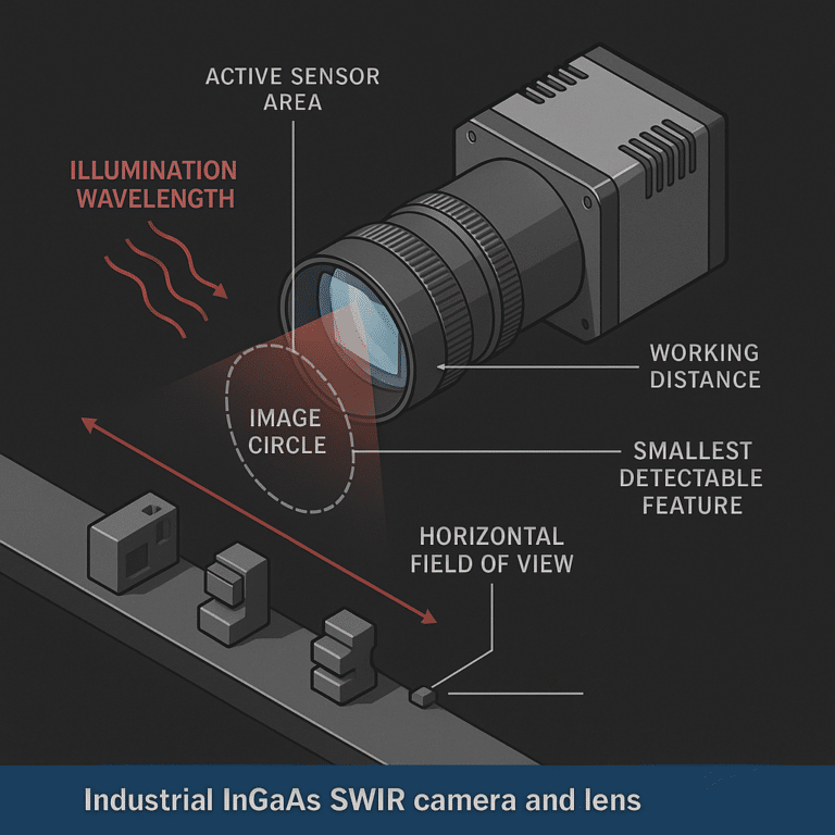
Record sensor model, active format, pixel pitch, mount, required field of view, working distance and allowable distortion. These inputs define image circle and resolution requirements. They also narrow the appropriate machine vision lenses for industrial SWIR inspection.
Step 2: Define illumination and target response
State whether illumination is broadband, narrowband or switched multispectral. Supply source curves, filters and target-response data where available. Identify the channel that drives the inspection decision rather than treating all wavelengths as equally important.
Step 3: Confirm lens, coating and window performance
Request assembled transmission, coating coverage, focus behavior and finished-window data on one wavelength axis. Apply minimum acceptable values to priority channels and flag unverified regions instead of filling gaps with assumptions.
Step 4: Validate optics and mechanics together
Prototype with the intended camera, illumination, filters, window and target. Check exposure margin, contrast, focus across field, channel-to-channel refocus, distortion, flare and temperature sensitivity. Mechanical fit remains necessary, but it is one acceptance category among several.
Common SWIR Spectral Matching Failures in OEM Imaging Systems
A mechanically compatible lens may have insufficient transmission or unresolved chromatic focus shift. A coating may be optimized outside the illumination band. A protective window may add loss or reflected artifacts. Most often, the underlying error is evaluating each datasheet independently rather than multiplying losses and testing the assembled path.
Another failure is accepting one transmission number without its wavelength. A value measured near the center of a passband says little about its edges or a second illumination channel.
When a Custom SWIR Optical Assembly Is the Better Option
Use custom design when requirements conflict
Custom engineering becomes reasonable when the required band, sensor resolution, field of view, working distance and enclosure cannot be met together by a catalog lens. It may also help when multiple illumination channels require controlled focus behavior or when a mandatory window changes the optical design.
Supply spectral requirements to the manufacturer
Provide sensor and source curves, target wavelengths, minimum throughput criteria, sensor format, pixel pitch, object distance, field of view, distortion limit, environmental window, mount and package envelope. A request for custom optical design for SWIR lens spectral matching is more actionable when unknowns and acceptance tests are identified explicitly.
Prototype the real optical stack
Validate the production-intent sensor, lights, coatings, filters and window together. If complete curves are unavailable, label the resulting performance as measured for that configuration rather than generalizing it to untested wavelengths or replacement components.
Frequently Asked Questions
Can one SWIR lens work across the full sensitivity range of an InGaAs sensor?
Possibly, but only if its assembled transmission, coatings, focus correction and image quality remain acceptable across that range. Sensor sensitivity alone does not define the usable band. Broadband operation should be verified at representative wavelengths, including band edges, with the intended filters, protective window, illumination and sensor.
Does a narrowband SWIR light source require a narrowband anti-reflection coating?
Not necessarily. A narrowband coating may improve performance around a selected wavelength, while a suitable broadband coating can support that wavelength plus future channels. Compare measured coating performance, incidence-angle range, environmental requirements and production tolerances. The correct choice follows the complete optical stack rather than the source label alone.
How do I compare two SWIR lenses when both list the same focal length and aperture?
Compare assembled transmission curves, coating bands, sensor coverage, resolution at the working wavelength, chromatic focal shift, distortion, working distance and environmental limits. Also confirm whether published data are typical or guaranteed. Identical focal length and f-number establish basic geometry, but they do not establish equal throughput, contrast or focus stability.
Can a camera housing window reduce SWIR image contrast even when it appears optically clear?
Yes. Human-visible clarity does not confirm SWIR transmission or low reflectance. The window material, coating, thickness, angle and surface quality may introduce absorption, reflections, ghosts or wavefront error. Review finished-window spectral data and test it in the production geometry with the intended lens, source, sensor and enclosure.
What information should an OEM provide when requesting a custom SWIR lens assembly?
Provide the sensor model, format and pixel pitch; illumination spectrum; target wavelengths; working distance; field of view; distortion and resolution limits; coating requirements; protective-window details; environment; mount; and package envelope. Include filters, expected volumes and measurable acceptance criteria so optical, spectral and mechanical trade-offs can be evaluated together.
Topics
Related Articles
SWIR Imaging for Moisture, Defects, and Material Inspection Systems
1 min read
Visible vs SWIR Lenses: Focus, Coatings, and Glass Materials
1 min read