Environmental Design Guide for Reliable SWIR Imaging Systems
A buyer-focused engineering guide to maintaining SWIR focus, alignment, and inspection repeatability across temperature, moisture, vibration, contamination, and mounting changes.
Key Takeaways
Reliable SWIR performance depends on treating the lens, sensor, window, enclosure, mount, cables, and operating environment as one system rather than qualifying each component separately.
- Define temperature, humidity, vibration, contamination, and warm-up conditions before freezing the optical and enclosure designs.
- Set measurable limits for focus, alignment, image quality, and inspection output instead of relying only on component environmental ratings.
- Control thermal gradients and condensation risk before adding lens or window heaters, because poorly distributed heat can introduce new focus errors.
- Validate windows, mounts, connectors, and cable routing with the production-intent assembly so interface stress is represented.
- Repeat environmental validation after changes to lenses, windows, seals, heaters, mounts, enclosures, cables, or image-processing settings.
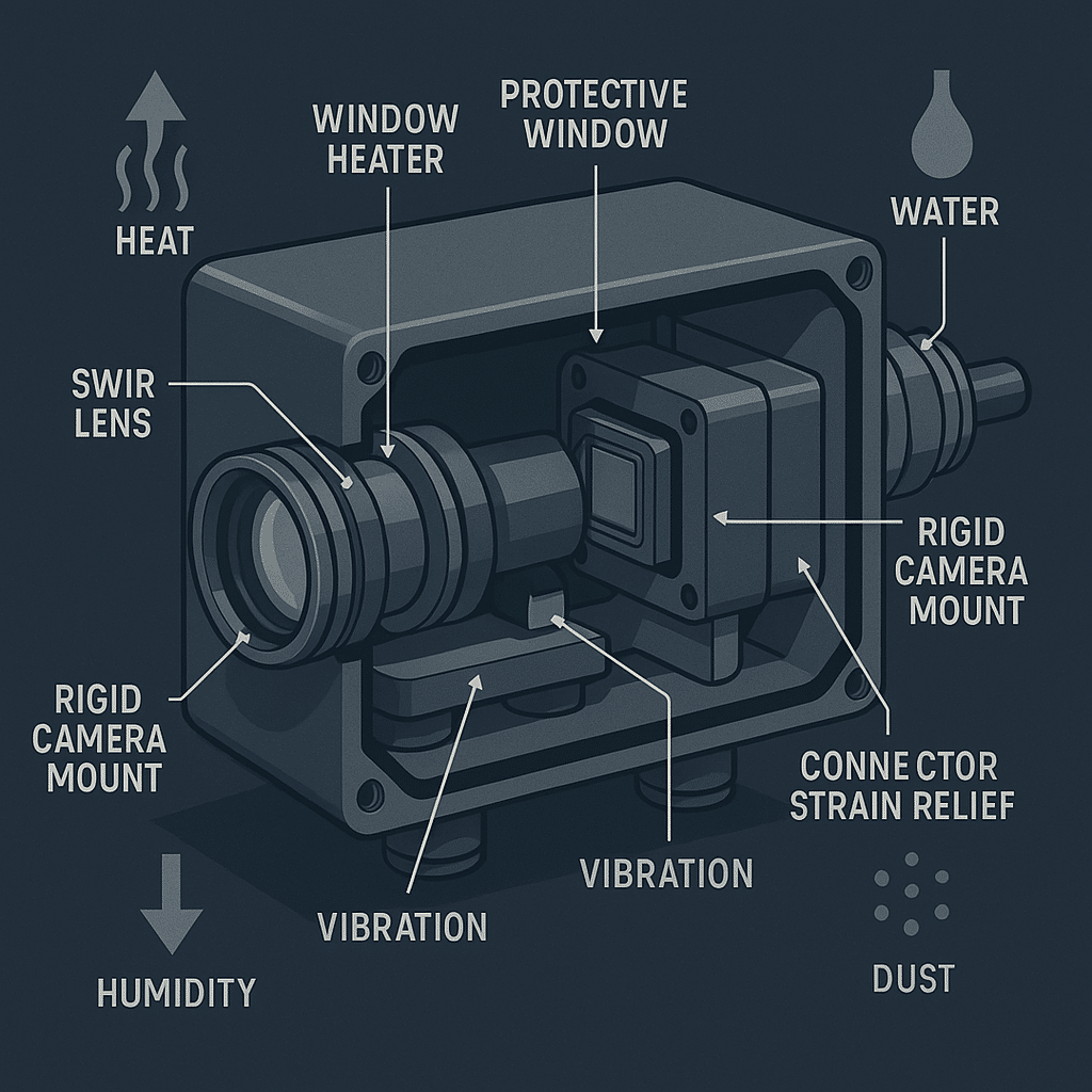
Reliable SWIR Imaging Systems require more than a camera and lens that meet separate environmental ratings. Temperature affects optical spacing and alignment; moisture can obscure surfaces; vibration can move threaded interfaces; and a stressed protective window can alter the optical path. The buyer-facing consequence may be intermittent focus loss, measurement drift, false rejects, or field recalibration.
Evidence basis: No verified external sources or approved company-document excerpts were supplied for this article. The mechanisms and design responses below are therefore presented as engineering guidance and qualified design inference, not as source-verified performance claims. Project limits must be established through analysis and testing of the production-intent system.
Environmental Risks That Affect SWIR Imaging Systems
Risk table: environmental condition, likely image symptom, design response, and validation focus
| Environmental condition | Potential impact on SWIR image stability | Components affected | Design considerations | Validation focus |
|---|---|---|---|---|
| Temperature variation | Focus shift, magnification change, alignment drift | Lens, sensor mount, barrel, enclosure | Match materials and tolerances; allow refocus or compensation where needed | Image quality and inspection output at temperature limits and during transitions |
| Thermal gradients and self-heating | Local focus drift or changing image uniformity | Sensor, electronics, lens mount, window | Provide controlled heat paths; avoid placing heat sources asymmetrically | Cold start, warm-up, steady state, and repeated duty cycles |
| High humidity and condensation | Haze, contrast loss, unstable transmission | Lens surfaces, sensor cover, window | Limit moisture entry; manage trapped air and surface temperature | Humidity transitions, shutdown, restart, and condensation-prone conditions |
| Dust, oil, water, or cleaning exposure | Scattering, obscured features, inconsistent inspection | Exterior window, seals, enclosure joints | Select compatible seals and cleaning access; shield exposed surfaces | Representative contamination and cleaning cycles |
| Vibration and mechanical shock | Blur, decenter, loosened focus, intermittent connections | Lens retention, camera mount, connectors, cables | Lock adjustments; stiffen load paths; add strain relief | Powered image monitoring during vibration plus post-test alignment checks |
| Mounting stress and enclosure distortion | Tilt, asymmetric sharpness, shifted field of view | Camera flange, lens mount, window frame | Control flatness, torque, datum scheme, and interface compliance | Compare free-state and installed optical performance |
| Protective-window contamination or damage | Contrast loss, flare, localized defects | Window, coating, retaining hardware | Provide service access and controlled replacement | Image checks before and after cleaning or replacement |
| Outdoor weather and solar exposure | Thermal gradients, water entry, changing background response | Enclosure, window, seals, lens, electronics | Shade or insulate where appropriate; provide drainage and sealing | Combined solar, temperature, moisture, and operating-load scenarios |
Why environmental requirements should be defined before optical and enclosure design are finalized
Environmental requirements determine more than material selection. They influence focus strategy, barrel architecture, window position, heater layout, sealing interfaces, connector choice, cable routing, calibration access, and allowable warm-up time.
A vague requirement such as “outdoor capable” isn’t actionable. Engineering teams need operating and storage limits, transition rates, exposure duration, duty cycle, installation orientation, cleaning methods, and pass/fail image criteria. Define whether the system must operate immediately after startup or may stabilize first. That single decision can change the thermal-control and calibration approach.
How Does Temperature Affect SWIR Image Focus?
Thermal expansion, optical alignment, and focus shift
Temperature changes can alter lens-element spacing, barrel length, flange position, sensor location, and refractive behavior. If those changes don’t compensate for one another, the best-focus plane can move relative to the sensor. Differential expansion can also introduce tilt or decenter, producing one-sided softness rather than a uniform focus shift.
The appropriate response depends on depth of field, pixel sampling, working distance, field position, and the inspection algorithm’s tolerance. A system that still looks acceptable to an operator may no longer provide repeatable edge location or defect classification.
SWIR camera thermal stability and sensor-related image variation
The camera is part of the thermal stack. Electronics and sensor self-heating can change local temperatures after power-up, while image corrections may respond differently across operating states. Buyers should review SWIR camera thermal stability considerations for infrared camera lenses together with the camera’s warm-up behavior, cooling method, calibration functions, and mounting interface.
Don’t assign every temperature-related image change to the lens. Compare raw or minimally processed images where practical, record internal camera states, and separate focus movement from changes in offset, noise, uniformity, or processing.
Temperature range, thermal gradients, and warm-up behavior
A chamber reaching a target air temperature doesn’t prove that the lens, sensor, mount, and window have reached equilibrium. Record temperatures at relevant components and evaluate transient operation as well as stabilized endpoints.
A useful test sequence includes cold start, powered warm-up, hot restart, temperature ramp, soak, and return to reference conditions. The return step helps distinguish repeatable thermal behavior from permanent movement, loosened hardware, or calibration drift.
Control SWIR Lens Heating and Thermal Gradients
When SWIR lens heating may be needed
Heating may be justified when exposed optical surfaces can fall below the local condensation threshold, when startup focus must be repeatable, or when the environment changes faster than passive thermal equalization can manage. It isn’t automatically beneficial. Added heat can create gradients, increase power demand, and move focus away from the state used for calibration.
Avoiding uneven heating across lenses, mounts, and protective windows
A heater concentrated on one side of a barrel or window can create asymmetric expansion. Nearby electronics may do the same unintentionally. Model or measure heat paths through the lens mount, enclosure wall, window retainer, seals, and camera body. Insulation can reduce heat loss but may also trap camera-generated heat.
Heater placement, control strategy, and focus verification
Control to a temperature measured near the component being protected, not merely to enclosure air. Define sensor placement, control hysteresis, failure behavior, maximum permitted temperature, and startup logic. Verify focus while the heater cycles; a pass at steady state can conceal periodic movement during control transitions.
Design SWIR Imaging Humidity Protection and Sealing
Condensation and moisture risks at optical surfaces
Condensation can form on the outside of a window, inside an enclosure, or on an internal optical surface if its temperature crosses the local dew point. Sealing alone may trap humid assembly air. SWIR imaging humidity protection therefore needs an assembly-environment plan as well as gaskets and sealants.
Sealing interfaces, enclosure design, and service access
Map every interface: window retainer, camera panel, connector, cable gland, focus adjustment, fastener penetration, and service cover. Decide which interfaces are permanent and which must reopen. A serviceable joint needs a repeatable seal-compression method and a way to confirm that maintenance hasn’t shifted the optical alignment.
Material compatibility also requires project-specific review. Cleaning agents, oils, sealants, coatings, and elastomers can interact even when each is acceptable in isolation.
Managing humidity changes during startup, shutdown, and washdown exposure
Startup can warm internal air before exterior optical surfaces warm; shutdown can reverse the gradient. Washdown adds rapid cooling, pressure, and possible chemical exposure. Test these transitions in the intended orientation and operating state. Include drainage and avoid geometries where water can remain against a seal or window edge.
Specify SWIR Protective Windows Without Compromising Image Stability
Window material, transmission range, and coating considerations
A window must transmit the system’s actual working band, not merely be described as infrared-compatible. Evaluate substrate transmission, thickness, surface quality, coating band, angle of incidence, temperature exposure, cleaning chemistry, and supplier tolerances. Detector response, illumination spectrum, and coating performance should be reviewed together.
Window tilt, mounting stress, and unwanted reflections
A window can introduce ghost images, focus effects, distortion, or field-dependent error. Tilting may redirect reflections but can add lateral displacement or aberration, especially with thicker windows or converging beams. Retaining force and seal compression can deform the optic. These trade-offs should be assessed through SWIR protective windows and custom optical design rather than treating the window as enclosure hardware alone.
Contamination, cleaning exposure, and window replacement planning
Specify acceptable contamination, inspection method, cleaning tools, chemicals, and replacement criteria. If field damage is likely, make the sacrificial window replaceable without disturbing lens focus or camera alignment. Use positive datums and controlled fastener torque, then require an image check after replacement.
Build Vibration-Resistant SWIR Systems
Vibration sources that affect focus, alignment, and repeatability
Fans, pumps, conveyors, vehicle structures, doors, and nearby machinery can impose different frequencies and directions. Motion during exposure may blur the image; longer-term vibration may loosen adjustments or wear cables. Shock can cause a permanent field shift without visible external damage.
Lens retention, camera mounting, and connector strain relief
For vibration-resistant SWIR systems for industrial inspection, review threaded focus locks, retaining rings, adhesive use, flange stiffness, fastener preload, connector retention, and cable strain relief. Keep cable forces from acting as a variable side load on the camera. Any locking method must remain serviceable to the degree required by the maintenance plan.
Mounting stress and its effect on optical performance
A rigid mount isn’t automatically a stable mount. An uneven enclosure surface or uncontrolled screw torque can distort the camera body, tilt the sensor interface, or pull the lens axis away from the intended datum. Measure image quality before installation, after installation, and at specified mounting torques. This isolates interface-induced errors from optical build variation.
Convert Operating Conditions Into Design Requirements
Define the operating envelope for temperature, humidity, shock, vibration, and contamination
Replace broad labels with bounded conditions and events. State operating and storage temperatures, transition behavior, humidity and condensation exposure, vibration sources, shock events, contamination type, cleaning process, solar load, altitude if relevant, and installation orientation. Connect each condition to a required operating mode and image result.
Assign requirements across the lens, camera, window, mount, enclosure, and cable system
Use an interface matrix to assign ownership. For example, the enclosure team may control water exclusion, the optical team window geometry, and the software team focus metrics. Someone must still own combined performance. SWIR environmental design for machine vision lenses should account for the sensor, illumination, mechanics, and algorithm rather than end at the lens flange.
Identify conditions that require active control, recalibration, or mechanical isolation
Consider a production line that starts cold, warms under continuous operation, and experiences periodic motor vibration. A practical requirement could call for image-quality verification at startup, a defined stabilization state, powered vibration testing, and a recalibration trigger after mount service. The exact limits must come from the application—not a generic lens specification.
Use passive compensation when it can cover the operating envelope without excessive cost or sensitivity. Consider active heating, refocus, software correction, or isolation when passive measures can’t meet the acceptance criteria. Each active measure adds controls, failure modes, and validation work.
Validate Environmental Reliability Before Production Release
Test image quality, focus, alignment, and inspection repeatability under environmental change
Measure outputs tied to the business task: focus metric, modulation or contrast target response, field position, magnification, distortion, defect-detection rate, measurement variation, or false decision rate. Preserve reference images and configuration data. Visual judgment alone is difficult to audit and may miss gradual drift.
Evaluate combined stresses rather than isolated conditions only
Separate tests help diagnose mechanisms, but field conditions overlap. Heat may soften a retention method while vibration is present; moisture may appear during a thermal transition; cable stiffness may change with temperature. Run selected combined-stress tests on production-intent assemblies after component-level screening.
Document acceptance criteria and revalidation triggers for field changes
The validation plan should state sample configuration, fixtures, operating mode, stabilization rules, measurement method, pass/fail limits, and post-test inspection. Revalidation triggers commonly include changes to the lens, camera, window, coating, seal, heater, mount, enclosure, cable, firmware, calibration, or cleaning process. The required scope should follow the affected interfaces and failure mechanisms.
Work With an Optical Partner on Environment-Specific SWIR Design
Information to provide during an OEM optical design review
Provide camera and sensor details, working band, illumination, field of view, working distance, resolution target, depth range, envelope constraints, interface datums, operating orientation, environmental envelope, warm-up allowance, service concept, production volume, and validation goals. Include known failure symptoms from prototypes, while separating observations from suspected causes.
When a custom optical assembly is appropriate
A custom assembly may be appropriate when standard optics can’t satisfy the combined spectral, packaging, focus-retention, sealing, window, or mounting requirements. The decision should compare non-recurring engineering, unit cost, lead time, serviceability, and qualification effort against the cost of adapters, active correction, recalibration, or field failures.
OEM engineers, security integrators, and machine builders can submit their operating conditions, camera and sensor information, field-of-view requirements, enclosure limits, and validation targets for a review of SWIR lens heating and optical lens assembly options. The review should close with explicit assumptions, interface ownership, acceptance criteria, and unresolved risks.
Frequently Asked Questions
What environmental information should an OEM provide when requesting a SWIR optical assembly?
Provide the minimum and maximum operating and storage temperatures, ramp rates, humidity and condensation exposure, shock and vibration sources, contamination, cleaning chemicals, duty cycle, warm-up allowance, sensor format, pixel pitch, field of view, working distance, enclosure geometry, window details, mount interfaces, cable loads, and measurable image-acceptance criteria.
When should a SWIR system use a replaceable protective window?
Use a replaceable window when the exposed optic faces recurring abrasion, impact, deposits, aggressive cleaning, or contamination that would make replacing the primary lens costly or disruptive. The design should locate the replacement repeatably, control seal compression and fastener torque, and require an image-quality check after service.
What should be included in a field-service plan for sealed SWIR camera enclosures?
Include approved opening and cleaning procedures, replacement seals, torque requirements, contamination controls, desiccant or purge instructions where applicable, leak-check methods, alignment references, focus and image tests, calibration steps, approved spare parts, service records, and clear triggers for factory return rather than field repair.
How can OEM teams compare environmental risk between indoor, mobile, and outdoor SWIR deployments?
Compare defined exposures rather than deployment labels. Score temperature range and transition, humidity, condensation, solar load, water and dust exposure, vibration spectrum, shock events, cleaning, contamination, cable motion, service access, and required startup time. Then rank each condition by likelihood, image consequence, detectability, and mitigation difficulty.
When is a custom lens mount preferable to adapting a standard camera mount?
Choose a custom mount when an adapter would add excessive tolerance stack, compliance, thermal mismatch, sealing difficulty, cable interference, or uncontrolled stress. A custom design can consolidate datums and retention features, but it also adds tooling, qualification, supply-chain, and service obligations that should be justified against measurable system requirements.
Topics
Related Articles

SWIR Lens Spectral Matching: Sensor, Lighting, and Coatings
10 min read
SWIR Imaging for Moisture, Defects, and Material Inspection Systems
10 min read