How Line Scan Imaging Works: Motion, Encoders, and Image Capture
Learn how a line scan camera converts successive sensor lines into a two-dimensional inspection image—and how motion, encoders, exposure and optics determine whether that image remains geometrically useful.
Key Takeaways
A defensible Line Scan Imaging specification connects the required object-space sampling to motion, trigger timing, exposure, data handling and lens performance rather than selecting each component independently.
- Calculate the required line rate from maximum target speed and the desired sampling distance in the direction of motion.
- Use position-based encoder triggering when speed variation would otherwise stretch or compress inspected features.
- Confirm whether the line trigger, frame trigger and exposure controls are generated by the camera, frame grabber, motion controller or PLC.
- Verify that exposure completes before the shortest expected trigger interval and that illumination provides adequate contrast within that time.
- Approve the lens only after fixing sensor length, pixel size, inspection width, working distance, wavelength and mechanical limits.
The Short Answer
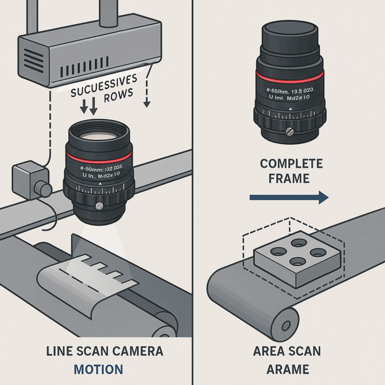
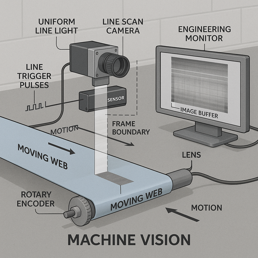
Line Scan Imaging builds a two-dimensional inspection image one sensor row at a time. Relative motion carries a web, product, cylindrical surface or camera past the imaged line. Each exposure records a narrow cross-section, and the acquisition system places successive rows into an image buffer. A free-running clock can set the line rate when speed is stable; encoder feedback instead ties each line to an increment of physical travel. A line trigger controls individual row capture, while a frame trigger starts or identifies a sequence. Useful results depend on matching motion, sampling distance, exposure, illumination, data bandwidth and lens coverage.
What Is Line Scan Imaging?
A line scan camera uses a single row of photosensitive pixels rather than a two-dimensional sensor array. It captures one narrow cross-section of the target, waits for the next acquisition event and captures another. A frame grabber or onboard processing device then buffers and assembles those rows into a continuous two-dimensional image, as described in this technical guide to line scan camera systems.
Controlled relative motion supplies the image’s second dimension. The product can move beneath a fixed camera, the camera can traverse a stationary product, or a cylindrical target can rotate. Without motion, repeated acquisition of a stationary target produces repeated rows rather than new spatial information.
How a Line Scan Camera Builds an Inspection Image
Across the sensor, pixel count and optical magnification determine sampling over the inspection width. Along the direction of travel, the distance moved between lines determines sampling. Software places the first captured line in one image row, the next line below it, and continues until an acquisition boundary or configured image length is reached.
Geometry fails when motion and capture lose synchronization. If the object travels farther than expected between lines, features become compressed in the assembled image’s travel axis. If it travels less, they appear stretched. Research published by Vision Systems Design on line-scan synchronization notes that even minor speed variations can distort imaged features when rows aren’t captured at regular surface intervals.
A practical specification therefore needs two sampling values: one across the sensor and one in the motion direction. Assuming square object-space sampling because the camera has square pixels is an engineering error; the along-motion value is set separately by travel per line.
The Core Components of a Line Scan Image Acquisition System
A complete acquisition chain normally includes:
- Camera and sensor interface: expose and read each sensor line, then transport the data.
- Lens and optical assembly: cover the sensor length while producing the required inspection width and object-space detail.
- Illumination: establish contrast within the available exposure time and over the full scan width.
- Motion source: move a web, conveyor product, rotating surface or camera at a measurable rate.
- Timing source: provide a free-running clock, encoder-derived pulses or controller-generated triggers.
- Acquisition hardware and software: receive, buffer, assemble and process the lines.
These aren’t independent purchasing decisions. A higher motion speed demands a higher line rate for unchanged sampling. That reduces the time available between line events and can constrain exposure. The shorter exposure can, in turn, change the required lighting output. More lines per second also increase the data-handling requirement.
The optical package must cover the complete linear sensor and sustain useful resolution across that length. Long sensors can be harder to serve than typical area sensors; short focal lengths may add distortion and reduce relative illumination. Buyers evaluating line scan lenses for industrial inspection should provide sensor length and pixel size, not only the camera mount.
Encoder Feedback and Its Role in Image Capture Timing
An encoder measures increments of motion at a rotating shaft or linear axis. Its pulses can trigger camera lines directly or pass through a motion controller, camera or frame grabber that scales the pulse stream. Position-based triggering keeps the nominal distance between lines tied to travel rather than elapsed time.
Free-running acquisition can be sufficient when speed is stable enough for the permitted geometric error and no precise registration is required. That is a project-specific tolerance decision, not a universal speed threshold. Encoder triggering is usually the stronger architecture when conveyor velocity changes, feature dimensions must remain consistent, or capture must stay registered to mechanical position.
Encoder presence alone doesn’t guarantee correct sampling. Resolution at the measured axis, gearing, coupling, pulse multiplication or division, electrical compatibility and trigger acceptance rate all matter. Slip between the encoder’s measured shaft and the target can also break the assumed position relationship. Engineering inference: if the encoder doesn’t measure true target travel, its pulses can be repeatable while the image scale remains wrong.
Line Trigger vs Frame Trigger: What Is the Difference?
A line trigger requests capture of an individual sensor line. It may come from an encoder-derived position pulse, a motion controller or an internal camera clock. A frame trigger starts, enables or marks an acquisition sequence—for example, the passage of one discrete product or the beginning of a defined web section.
The two signals can work together. A product sensor or PLC event opens a frame, encoder pulses request its individual lines, and a configured line count or end event closes it. Continuous-web systems may instead acquire indefinitely and let software divide the stream into process-relevant regions. Trigger meanings and supported modes remain camera- and acquisition-device-specific, so the selected hardware manuals govern the final implementation.
Line Scan Integration Dependencies: Inputs, Responsibilities, and Buyer Questions
| System element | What it controls | Typical integration dependency | Buyer question before approval |
|---|---|---|---|
| Line scan camera | Exposure, readout and data output | Interface, trigger modes, line rate and exposure control | Can it accept the planned signals at the required rate? |
| Encoder feedback | Position-based line timing | Pulse resolution, coupling, scaling and input compatibility | Does each accepted pulse represent the required target travel? |
| Motion system | Relative target movement | Speed variation, acceleration, vibration and alignment | How is timing maintained during speed changes? |
| Lighting | Contrast and exposure margin | Uniformity, working distance, thermal limits and strobe behavior | Is output sufficient across the scan width at the allowed exposure? |
| Lens assembly | Field of view, sensor coverage and geometry | Sensor length, pixel size, wavelength, distance and mount | Is required detail maintained across the entire line? |
| Acquisition stack | Transfer, buffering and image assembly | Bandwidth, trigger handling, memory and configuration | Can it process production data without dropped lines? |
Timing ownership should be documented. Identify which device generates each signal, which device scales encoder pulses, accepted voltage or signaling type, edge polarity, latency assumptions and behavior when triggers arrive too quickly. Leaving this boundary to commissioning can force changes across the camera, controller and cabling.
How to Set Image Capture Timing for a Line Scan System
For initial sizing, the verified design relationship is:
Required line rate = target velocity ÷ desired along-motion sampling distance
Worked example: a target moving at 2 m/s with desired sampling of 0.1 mm per line requires 20,000 lines/s. This is a design calculation, not a camera recommendation. Margin may be needed for speed tolerance, trigger scaling and the camera’s supported operating modes.
At 20,000 lines/s, the nominal interval is 50 microseconds. The programmed exposure must be shorter than the minimum trigger period; otherwise, a new trigger can arrive before the previous exposure finishes. Depending on camera behavior, that trigger may be ignored or delayed, producing missing or displaced scans. Exposure also controls motion blur, so shortening it can improve motion freezing but reduces collected light.
Verification should cover more than steady production speed:
- Measure or calculate the fastest target condition and shortest trigger interval.
- Confirm the camera can accept that line rate in the intended trigger and exposure mode.
- Check encoder scaling against actual target travel rather than shaft travel alone.
- Exercise acceleration, startup, stopping and speed transitions.
- Monitor for dropped, duplicated or delayed rows while the acquisition stack is under processing load.
Optical and Mechanical Dependencies That Affect Image Quality
Lens selection starts with sensor length, pixel size, required scan width and working distance. Magnification links the object width to the active sensor length; the selected lens must then resolve the required object detail across the line. This machine vision lens selection by field of view and sensor framework helps organize those inputs before focal length is proposed.
Distortion matters because position varies across a long linear field. Calibration may correct some repeatable geometric error in software, but it doesn’t recover unresolved detail or eliminate an inadequate image circle. Relative illumination also deserves evaluation at the ends of the sensor, where insufficient optical or lighting coverage can reduce usable contrast.
Mechanical behavior can defeat a correct optical calculation. Vibration changes the camera-to-target relationship; web flutter or target-height variation changes object distance and scale. The appropriate tolerance depends on depth of field, defect size and measurement requirement. Engineering inference: specifying only nominal working distance hides the mechanical range that the optical design must tolerate.
Questions to Resolve Before Approving a Line Scan Optical Package
An RFQ should define the inspection problem and its interfaces, not merely request a focal length. Include:
- active sensor length, pixel size, camera mount and interface;
- required inspection width, smallest relevant feature and permitted geometric error;
- nominal and maximum target speed, acceleration profile and stop-and-go behavior;
- working distance plus target-height or web-position tolerance;
- encoder location, pulses per unit travel and planned scaling;
- line-trigger and frame-trigger sources, electrical format and timing owner;
- wavelength, lighting geometry, exposure range and environmental limits;
- expected image length, line rate, data format and processing platform.
Responsibility boundaries belong in the specification. The optics supplier can assess coverage and imaging performance only against defined sensor, geometry and wavelength inputs. The controls team owns signal generation and motion behavior; the camera and acquisition suppliers must confirm trigger handling and bandwidth. For unusual mechanical or spectral constraints, package these requirements when requesting custom optical lens assemblies.
When Line Scan Imaging Is the Right Architecture
Line-based capture is well suited to continuous webs, long products, rotating cylindrical surfaces and wide inspections where relative motion already exists. It can also separate inspection width from image length: the sensor defines one dimension while travel defines the other.
An area camera may be simpler when the complete target fits in one field, objects can be stopped, motion is poorly controlled, or a single exposure provides the required evidence. Architecture should be decided before the lens package because the sensor geometry, illumination and timing model change with it. Use this line scan vs area scan imaging system selection comparison when motion and inspection geometry are still open.
Planning a line-based inspection station? Share the sensor format, scan width, working distance, target speed, encoder and trigger approach, lighting wavelength and environmental constraints so Superior can help evaluate an appropriate lens or optical assembly.
Frequently Asked Questions
Can a line scan camera operate without an encoder?
Yes. A camera can run from its internal line clock or another periodic trigger when motion is sufficiently stable for the allowed geometric error. Without position feedback, speed changes alter the distance represented by each row. Validate the free-running approach across the complete production speed range, not only at nominal speed.
What happens if conveyor speed changes during line scan image acquisition?
With time-based capture, changing speed changes target travel between lines, stretching or compressing features in the motion direction. Encoder-derived triggers can preserve nominal spatial spacing if the encoder accurately represents target travel and the camera accepts every pulse. Exposure and trigger-rate limits still require checking at maximum speed.
Does every line scan system need both a line trigger and a frame trigger?
No. Continuous systems may use only line events and let software segment the resulting stream. Discrete-product systems often use a frame-level event to start or identify a sequence, then use line triggers for individual rows. The necessary arrangement depends on the camera’s modes, product tracking and required image boundaries.
How does sensor pixel size affect line scan lens selection?
Pixel size helps define the sensor’s sampling capability and the lens resolution needed to use it. It must be considered with sensor length, magnification, inspection width and the smallest relevant object feature. Small pixels alone don’t guarantee more resolved detail if the lens, focus, motion or contrast limits the system.
What should an OEM provide when requesting a custom line scan optical assembly?
Provide active sensor dimensions, pixel size, mount, inspection width, working-distance range, smallest relevant feature, wavelength and mechanical envelope. Also include target speed, exposure constraints, environmental conditions and anticipated production tolerances. Encoder and trigger details help reveal timing dependencies even when the request is primarily for the optical assembly.
Topics
Related Articles