


Optical Gauging Uncertainty: Lens, Calibration, and Environment
A buyer-focused framework for connecting lens performance, calibration, mechanics, lighting, software and operating conditions to a defensible dimensional-measurement claim.
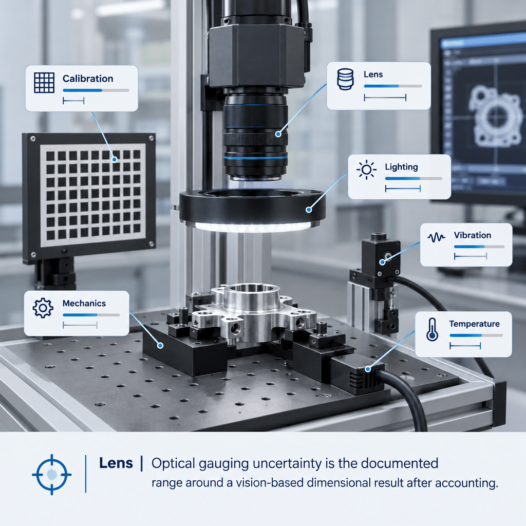
Key Takeaways
Optical Gauging Uncertainty must be evaluated as a complete measurement-chain problem rather than inferred from pixel size, lens distortion or repeatability alone.
- Require an uncertainty budget that converts every material contributor into units at the measured feature.
- Judge corrected distortion by verified residual error across the used field, not by the lens’s uncorrected distortion figure.
- Match calibration geometry, coverage and artifact documentation to the production measurement plane.
- Specify permissible temperature, vibration, part-height, lighting and focus ranges alongside the accuracy claim.
- Approve telecentric optics only when their reduction of depth-related magnification risk materially improves the total budget.
The Short Answer
Optical gauging uncertainty is the documented range around a vision-based dimensional result after accounting for optics, calibration, mechanics, illumination, environment, repeatability and software. Calculate it by defining the feature and operating conditions, identifying relevant systematic and random contributors, expressing each contributor in dimensional units at the part, and applying a documented combination rule. Pixel scale establishes sampling sensitivity, not total accuracy. The final claim should be validated across the used field of view, expected part positions, materials and environmental range, with traceable calibration evidence and stated decision limits.
What Is Optical Gauging Uncertainty?
For procurement purposes, uncertainty is the stated doubt surrounding a reported measurement under defined conditions. It is not interchangeable with error, accuracy or repeatability. Error is the difference from an accepted reference value; repeatability describes agreement among repeated results. An instrument may repeat closely while retaining an uncorrected bias.
Why pixel resolution is not measurement accuracy
Dividing object-space field width by the number of sensor samples gives a nominal object-space scale. That arithmetic does not account for edge contrast, distortion residuals, calibration uncertainty, depth variation, thermal movement or segmentation behavior.
Illustrative calculation, not a product claim: a 100 mm field sampled across 2,000 pixels has a nominal scale of 0.05 mm per pixel. If a particular edge detector repeats within 0.2 pixel under a stated test, the corresponding repeatability component is 0.01 mm. Neither result establishes total accuracy; the remaining contributors still require evidence.
The complete measurement chain
The result depends on the part and fixture, lens and camera, working geometry, illumination, calibration, triggering, image processing and operating environment. A purchase specification that names only sensor resolution and lens distortion leaves ownership of the largest unknowns unresolved.
How Do You Calculate Optical Gauging Uncertainty?
Start with the measurand: the exact diameter, gap, position or edge-to-edge distance being reported. Record its tolerance, measurement plane, field position, working distance, part-height range, cycle state and decision rule. “Measure the component accurately” is not a testable requirement.
Separate contributors that may create a persistent offset from those that vary between images or cycles. A calibration correction may address a detected bias, but the correction itself retains uncertainty. Repeatability testing captures variation only under the conditions exercised.
Convert each contributor into the same object-space unit at the measured feature. Pixel, angular and temperature-related inputs cannot be added meaningfully until the project’s model translates them into dimensional effects. The combination rule must also be documented. If a metrology procedure permits a root-sum-square treatment, its independence and distribution assumptions need justification; otherwise, use the approved conservative method.
Build an Optical Measurement Uncertainty Budget
A defensible optical gauging uncertainty budget connects each contributor to evidence, an owner and a control. “Included in calibration” is insufficient unless the calibration actually exercises that variable over its production range.
Optical Gauging Uncertainty Budget: Contributors, Evidence, and Risk Controls
| Uncertainty contributor | Measurement effect | Quantify or verify | Typical control | Evidence owner |
|---|---|---|---|---|
| Pixel scale and sampling | Limits dimensional sensitivity | Calibrated scale at relevant field positions | Suitable field, sensor and calibration | Vision integrator |
| MTF and edge localization | Changes edge contrast and repeatability | Repeated edge results using controlled images | Optics, focus and stable processing | Lens/camera supplier |
| Distortion residual | Position-dependent dimensional bias | Residual map after correction | Field calibration or lower-distortion optics | Calibration team |
| Magnification change with depth | Scale changes as part height varies | Test at permitted height limits | Geometry control or telecentric optics | Optical designer |
| Focus and aperture | Alters contrast and edge response | Challenge focus and depth range | Lock focus and aperture; control depth | Integrator |
| Calibration artifact accuracy | Transfers reference uncertainty | Artifact certificate and condition | Appropriate documented artifact | Quality team |
| Calibration coverage | Leaves untested field regions | Residuals across the used field | Match grid and placement to use | Calibration team |
| Mechanical stability | Moves camera, lens, fixture or part | Settling and repositioning study | Rigid mounts and controlled handling | Machine builder |
| Lighting and segmentation | Moves the detected boundary | Vary intensity and representative surfaces | Regulated lighting and robust features | Vision engineer |
| Cycle repeatability | Produces result spread | Repeated parts, positions and cycles | Process and fixture controls | Manufacturing |
| Temperature | Changes part, fixture or optical geometry | Test or model stated temperature range | Stabilize or compensate | System owner |
| Vibration and blur | Smears or displaces edges | Images and results during machine states | Isolation, exposure and settling control | Automation team |
| Software and thresholds | Changes feature interpretation | Versioned validation dataset | Lock versions and parameters | Software owner |
The table is a planning framework, not a universal claim that every term is equally material. Screening tests may show that some contributors are negligible for a particular feature and operating range. That decision should remain recorded rather than assumed.
Lens Specifications That Affect Optical Gauging Uncertainty
Sampling, MTF and edge localization
Nominal object-space scale answers how much field corresponds to one pixel. MTF concerns how contrast is transferred at spatial frequencies relevant to the feature. Edge location also depends on focus, illumination, noise and the algorithm. When comparing evidence, check image processing, chart quality and repeatability conditions; this overview of MTF test repeatability identifies useful supplier-review questions.
Distortion residuals matter after correction
A headline distortion percentage does not reveal the remaining dimensional error after calibration. Request a residual map or equivalent verification over the field actually used. Also separate geometric distortion from perspective caused by object-plane tilt or depth. The distinction is central to a valid lens distortion calibration plan because software correction of one mechanism does not automatically remove the other.
Telecentricity, focus and aperture
Object-space telecentric optics can reduce magnification sensitivity to object-distance variation within their designed operating range. They do not eliminate calibration, focus, alignment, artifact or environmental contributors. Aperture selection also involves a system trade-off: changing it affects light level, depth response and contrast, so validation should use the production setting rather than an unconstrained laboratory setup.
Calibration Artifact Accuracy and Calibration Method
Calibration artifact accuracy must support the intended result, but no universal artifact-to-tolerance ratio can be approved without the complete budget and applicable quality procedure. Ask for the artifact’s documented uncertainty, traceability information, calibration status, dimensional stability assumptions and usable area.
Match geometry and coverage to production
Place the artifact in the measurement plane and reproduce the intended field, focus, aperture and mounting state. A central scale calibration may be adequate for a narrow central measurement but cannot, by itself, characterize field-dependent residuals. Grid calibration is better suited to mapping spatial behavior; local feature calibration may be efficient when one constrained region controls the decision.
After calibration, inspect residuals by field position and direction using evidence not merely restating the fitted model. Recalibration or reverification should be triggered by changes capable of altering the measurement chain, including lens or camera replacement, mount disturbance, focus adjustment, software changes or a failed control check.
Environmental Effects on Optical Measurement
Temperature can affect the part, reference artifact, fixture, lens barrel, camera position and focus state. Rather than assigning a generic thermal allowance, name the permitted operating range and determine which materials and dimensions influence the measurand.
Vibration risk depends on exposure timing, machine state, structural response and mechanical settling. Test during representative motion and dwell conditions, not only with the machine idle. Lighting variation can move a threshold-derived edge when surfaces are reflective, textured or curved. Representative finishes, contamination states and feature orientations belong in validation.
Dust, oil, condensation or protective-window damage may change contrast without causing an obvious camera fault. Maintenance criteria therefore need observable checks: optical-surface condition, illumination output, control-part results or another approved indicator.
Validate the Measurement System Before Claiming Micrometre Accuracy
Repeatability establishes result spread under the tested conditions. It does not, on its own, establish traceability or total uncertainty. Validation should cover the full used field, permitted part positions, working-distance variation and expected cycle states.
Challenge the system with production-representative edge direction, material, finish and geometry. A high-contrast calibration target may not predict segmentation behavior on a reflective machined edge. Keep separate records for calibration residuals, repeated measurements, reference comparisons and environmental challenges so one favorable result cannot conceal another failure mode.
The approved specification should state the uncertainty limit, operating envelope, calibration state, software version and decision rule. Where measurement uncertainty could overlap a tolerance boundary, define a guard-band policy rather than treating every displayed digit as conclusive.
When Telecentric Optics Are Justified for Dimensional Inspection
Telecentric optics are candidates when permitted part-height or placement variation would create unacceptable magnification or perspective sensitivity with a conventional lens. Evaluate telecentric lens measurement accuracy at the required field, working distance, depth range, aperture and feature contrast—not as an isolated lens label.
A conventional lens may remain sufficient when the measurement plane is tightly constrained, the field region is limited and residual behavior is calibrated and verified. The relevant commercial question is whether the reduced geometry risk offsets added size, working-distance and integration constraints. A telecentric vs conventional lens comparison can structure that review.
A Practical Review Checklist for Optical Gauging Projects
Supplier and integration inputs
Request:
- object-space field, working distance, sensor format and pixel pitch;
- distortion data and corrected residual evidence over the used field;
- contrast or MTF evidence under stated focus, aperture and image-processing conditions;
- telecentricity or magnification-versus-depth evidence where depth varies;
- mechanical interface, focus retention and production variation controls;
- calibration artifact documentation, placement method and recalibration triggers;
- validation data covering representative parts, positions and environments;
- software version, thresholds, parameter permissions and change control.
Translate these into drawing-level acceptance tests. The supplier’s optical lens quality acceptance criteria can inform questions about MTF, distortion, centering and lot consistency, while available machine vision lens options provide a starting point for optical architecture discussions.
Before approving an accuracy statement, identify who owns every budget line, what evidence closes it and which change reopens validation. Share the target feature, tolerance, field, working distance, part-height variation, rate and operating environment to request an optical gauging feasibility review.
Frequently Asked Questions
What is the difference between optical measurement uncertainty and repeatability?
Repeatability describes how closely repeated results agree under stated conditions. Optical measurement uncertainty is the documented doubt around the reported result after considering repeatability plus calibration, optics, mechanics, environment and software. A system can repeat tightly while remaining biased, so a repeatability study alone cannot substantiate dimensional accuracy.
How accurate does a calibration artifact need to be for a vision measurement system?
There is no defensible universal ratio. The artifact’s documented uncertainty must leave adequate room for all other contributors and the project’s decision rule. Evaluate its certified features, usable area, condition, placement and environmental assumptions against the intended measurement rather than selecting it only from the nominal part tolerance.
Can software correction eliminate lens distortion measurement error?
Software can compensate for a characterized distortion model, but it cannot guarantee zero residual error. Results still depend on calibration coverage, artifact quality, model fit, focus, geometry and stability after calibration. Verify corrected residuals across the used field and distinguish lens distortion from perspective or parallax caused by object placement.
Does a telecentric lens guarantee measurement accuracy?
No. A suitable telecentric lens can reduce magnification changes associated with object-depth variation, but total accuracy still depends on calibration, alignment, sampling, contrast, mechanics, lighting, software and environment. Its benefit should be measured within the complete system budget at the specified field, working distance and depth range.
How often should an optical gauging system be recalibrated?
Use an interval supported by stability history, risk and the applicable quality procedure rather than a universal calendar rule. Recalibrate or reverify after changes that may affect geometry or processing, such as component replacement, mount disturbance, focus adjustment or software revision, and whenever control checks exceed their approved limits.
Topics
Related Articles
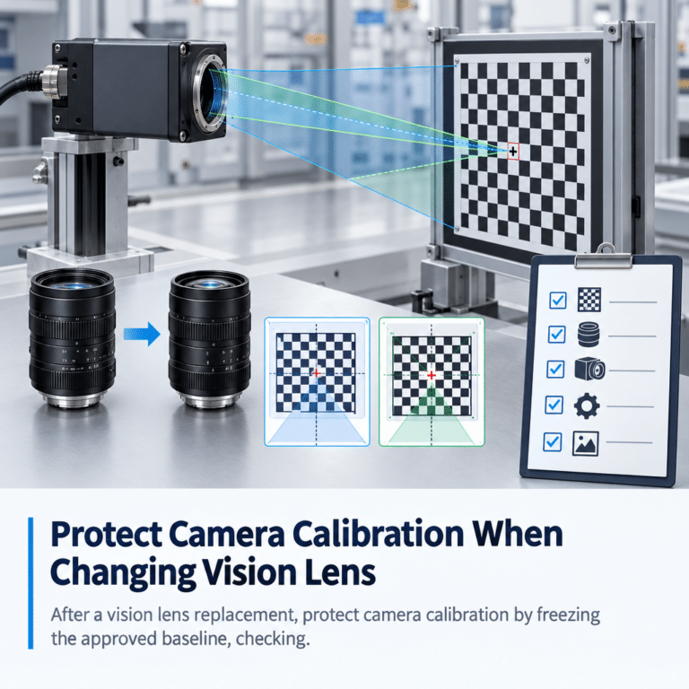
How to Protect Camera Calibration When Changing Vision Lenses
12 min read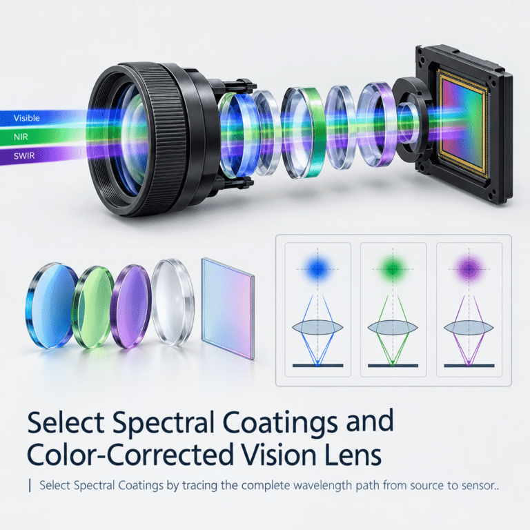
How to Select Spectral Coatings and Color-Corrected Vision Lenses
10 min read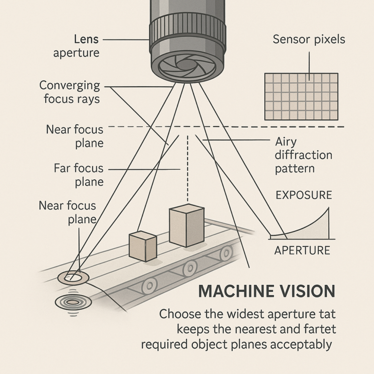
How to Balance Aperture, Depth of Field, and Diffraction in Vision
10 min readAbout SUPERIOR OPTICS
SUPERIOR OPTICS specializes in CCTV lenses, machine vision optics, and custom optical solutions for security, industrial imaging, and specialty applications. We also provide professional lens selection and application support.