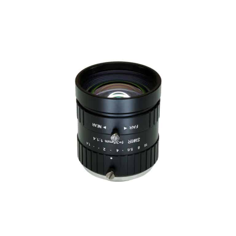
How to Select a SWIR Lens for InGaAs Camera Inspection Systems
A practical engineering method for turning inspection requirements, InGaAs sensor data, working distance, wavelength, and target resolution into a supplier-ready SWIR lens specification.
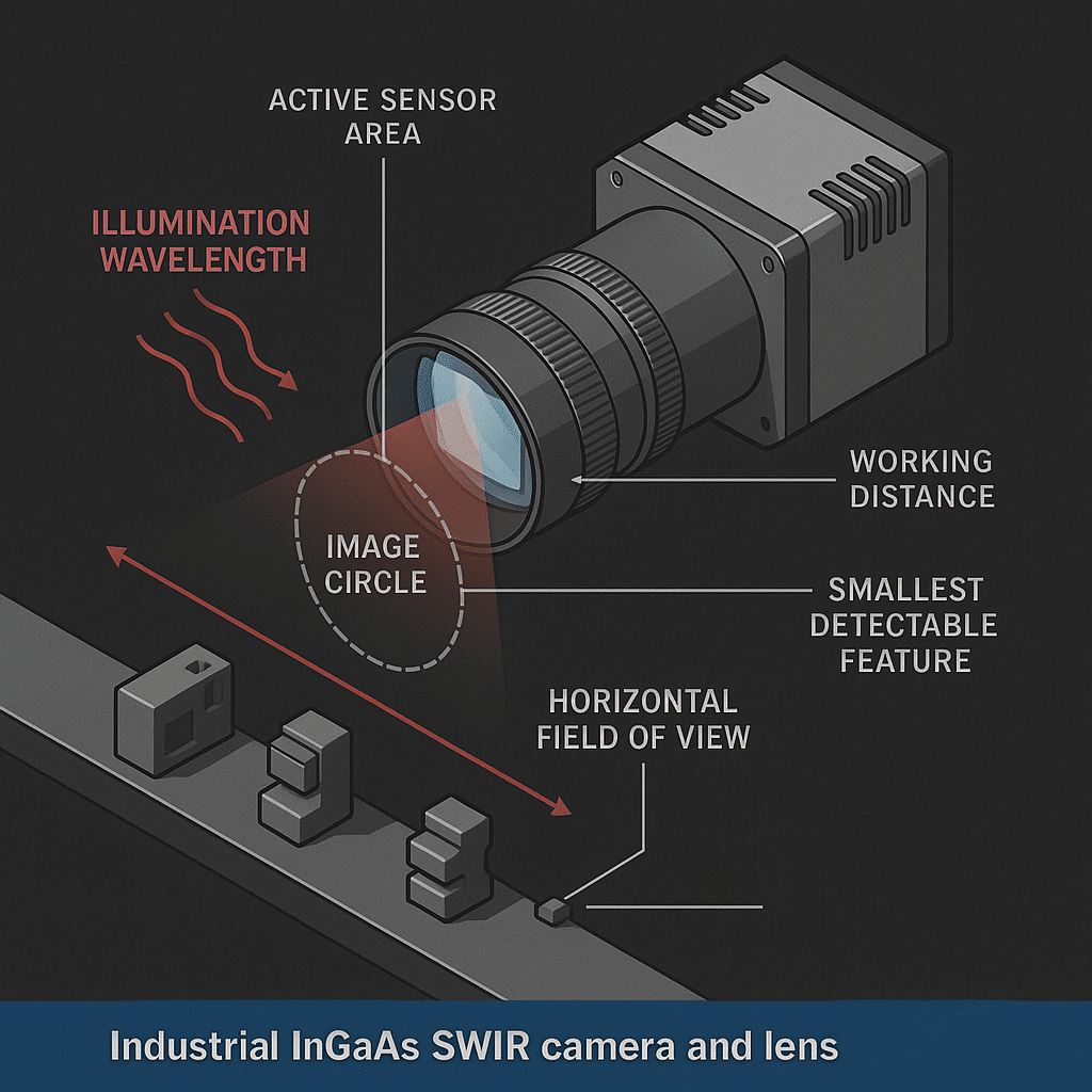
A SWIR Lens should be specified from the inspection target backward—not selected from focal length alone. The engineering sequence is to define the smallest relevant feature, confirm the InGaAs sensor’s active area, set field of view and working distance, identify the operating wavelengths, and then verify sampling, aperture, image circle, mount, and environmental limits.
That sequence matters because InGaAs camera inspection systems are not interchangeable. Standard cameras commonly operate around 900–1700 nm, while extended-range designs may reach 1900 or 2200 nm. The lens must be corrected for the band actually used, not merely labeled “infrared.” Axiom Optics also distinguishes reflected-light SWIR imaging from MWIR and LWIR systems that detect emitted heat.
To select a SWIR lens for an InGaAs camera:
- Define the inspection target and smallest defect or feature.
- Confirm active sensor width, height, pixel count, and pixel pitch.
- Calculate the required horizontal and vertical field of view.
- Estimate focal length from field of view and working distance.
- Match lens transmission and correction to the illumination band.
- Verify resolution, aperture, image circle, mount, filters, and packaging.
Key Takeaways
- Use active sensor dimensions, not a nominal fractional-inch format.
- Treat focal-length equations as first-pass estimates; distortion and finite conjugates require validation.
- Specify wavelengths used by the inspection, including multispectral switching—not just the camera’s full sensitivity range.
- Allocate several pixels across the smallest target unless testing proves a lower sampling threshold reliable.
- Approve the lens using representative parts, lighting, exposure, distance variation, and production tolerances.
Start With the Inspection Requirement, Not the Lens
Define the defect, feature, or material property to be detected
State what produces the decision signal: an inclusion, fill level, moisture-related contrast, coating difference, edge, foreign material, or dimensional boundary. Record whether the task is detection, classification, or measurement. Measurement generally demands tighter control of distortion, calibration, and object position than simple presence detection.
Document target size, inspection area, and allowable measurement error
Define the smallest relevant feature in object-space units and the full area that must appear in one image. Include object-height variation, conveyor wander, fixture tolerance, and any exclusion zone near the image edge. A lens that covers the nominal part but clips a shifted part has not met the system requirement.
Set required image resolution in pixels across the target
A one-pixel indication is fragile because blur, noise, interpolation, focus drift, and target alignment can reduce contrast. A practical starting requirement might be multiple pixels across a defect, but the correct threshold depends on contrast and the vision algorithm. That threshold is an engineering assumption until representative samples are tested.
Step 1: Confirm the InGaAs Sensor Format and Active Area
Collect sensor width, height, pixel pitch, and pixel count
Obtain the camera drawing and sensor data. If only pixel count and pitch are available, calculate active width and height:
Sensor width = horizontal pixels × pixel pitch
Sensor height = vertical pixels × pixel pitch
For example, 640 horizontal pixels at 15 µm pitch produce an active width of 9.6 mm. This is a calculation, not a claim about a particular camera.
Use the active sensor area rather than nominal optical format
Terms such as “1-inch format” are category labels and do not reliably provide the physical dimensions needed for optical calculations. Base coverage and magnification on the manufacturer’s active-area dimensions.
Check the lens image circle for full sensor coverage
The specified image circle should cover the active sensor diagonal at the intended focus condition. Coverage alone is insufficient: request information or samples addressing edge sharpness, illumination falloff, distortion, and any sensor cover glass or filter stack that could alter performance.
Step 2: Calculate the Required Field of View and Magnification
Calculate field of view from the required inspection area
Field of view is the object-plane area the system must image. Add only justified process margin; excessive field of view reduces object-side sampling because the same pixels cover a larger area.
Object sampling = object field of view ÷ pixel count
A 100 mm horizontal field captured by 640 pixels gives 0.156 mm per pixel. A 0.5 mm feature spans about 3.2 pixels before optical blur and processing effects are considered.
Determine magnification from sensor size and object size
Magnification m = sensor dimension ÷ object field dimension
A 9.6 mm-wide sensor imaging a 100 mm-wide object field requires approximately 0.096× magnification. Calculate both axes. The axis producing the tighter requirement governs unless cropping is acceptable.
Use SWIR lens field of view calculation to prevent coverage gaps
A SWIR lens field of view calculation should include minimum and maximum working distance, object-position tolerance, and sensor orientation. Verify the result physically because catalog field angles may be stated at infinity or under conditions different from the inspection setup.
Step 3: Determine Focal Length From Working Distance and Field of View
Estimate focal length using sensor dimension, working distance, and field of view
f ≈ sensor dimension × working distance ÷ field of view
With a 9.6 mm sensor width, 300 mm working distance, and 100 mm horizontal field, the estimate is 28.8 mm. This simplified geometry does not account for principal-plane location, distortion, lens breathing, or finite-conjugate optimization. Use it to shortlist lenses, then confirm against lens data or ray-trace results.
Select the governing sensor dimension
Use horizontal dimensions when line coverage controls, vertical dimensions when product height controls, and the diagonal when corner coverage is mandatory. Do not mix sensor width with vertical field of view.
Allow mechanical margin
A machine specified at 300 mm working distance may operate at 295–305 mm after assembly and product variation. Check field coverage and focus across that range. Moving the camera later can change enclosure clearance, illumination angles, and calibration, so optical margin should be designed rather than improvised.
Step 4: Match the SWIR Lens Wavelength Range to the Inspection Task
Identify the illumination wavelengths
List the source wavelengths, bandwidths, filters, and whether images are taken sequentially at multiple bands. The camera’s sensitivity range is not automatically the required lens band. A narrowband 1450 nm inspection and a 1000–1650 nm multispectral system impose different transmission and chromatic-correction requirements.
Verify transmission across the required SWIR lens wavelength range
Common glass can transmit some SWIR energy, but useful transmission does not guarantee acceptable image quality. Visible lenses may show wavelength-dependent focus errors in SWIR, while purpose-designed optics are optimized for the intended spectral region, according to Clearview Imaging.
Request transmission data for the complete lens, not just the glass type. Coatings, cement, filters, apertures, and element thickness all affect throughput. Review infrared lens options for wavelength-sensitive imaging when visible-band performance cannot be assumed.
Evaluate focus shift with multiple wavelengths
Focus the prototype at each operating wavelength without moving the camera. Compare target contrast at the center and edges. If refocusing is required between bands, determine whether the mechanism, cycle time, and calibration can tolerate it. An achromatized or custom design may be preferable when registration between wavelength channels matters.
Step 5: Specify Resolution, Pixel Sampling, and Aperture
Convert the smallest feature into object-side pixel coverage
Pixels across feature = feature size ÷ object sampling
If sampling is 0.156 mm per pixel, a 0.5 mm feature covers roughly 3.2 pixels. That calculation describes sampling, not detection probability. Validate with the actual material contrast, illumination, exposure, processing, and acceptable false-call rate.
Compare lens resolving capability with sensor pixel pitch
A small pixel pitch can preserve more spatial detail only if the lens delivers adequate contrast at the corresponding spatial frequencies. Ask suppliers for wavelength-specific MTF data at the intended aperture, field positions, and conjugate distance where available. A single “megapixel” rating does not describe center-to-edge performance or SWIR contrast.
Camera pixel count determines digital sampling, and higher sensor resolution can capture finer detail when the optics and signal quality support it. Frame rate also affects moving inspections because exposure and motion blur must fit the process speed, as summarized by Tech Imaging.
Balance aperture, depth of field, exposure time, and diffraction
Opening the aperture collects more light and can shorten exposure, but usually reduces depth of field and may reveal off-axis aberrations. Stopping down can increase focus tolerance until diffraction and reduced signal become limiting. Evaluate several f-numbers under production-like illumination rather than approving the lens at one favorable setting.
Step 6: Verify SWIR Camera Lens Compatibility Before Integration
Match mount, flange distance, and mechanical envelope
SWIR camera lens compatibility includes mount thread or bayonet, flange focal distance, focus travel, barrel diameter, rear-element clearance, locking method, and connector access. Compare controlled drawings—not just labels such as C-mount or M42. For industrial configurations, review machine vision lenses for industrial inspection setups.
Check image circle, chief-ray behavior, and sensor-edge performance
Confirm full active-area coverage at the specified conjugate. If the sensor has a cover window or filter, provide its material and thickness to the optical supplier. Edge response should be assessed with the actual camera because sensor architecture and filter stacks can interact with oblique rays.
Confirm filters, illumination geometry, and environment
Document the filter’s clear aperture, thickness, mounting location, spectral edges, and angle of incidence. Also identify temperature, vibration, contamination, humidity, cleaning agents, and whether focus and iris settings need locks. These requirements affect housing and qualification even when the nominal optical prescription is unchanged.
Build a Practical SWIR Lens Specification for Supplier Review
A useful request for quotation separates required performance from preferences. State the acceptance method, operating conditions, and tolerances. If information is provisional, label it rather than forcing a supplier to treat an estimate as fixed.
SWIR Lens Specification Checklist for InGaAs Camera Inspection Systems
| Specification Item | What to Define | Why It Matters | How to Verify |
|---|---|---|---|
| Camera sensor | Active width and height, pixels, pitch, mount | Sets coverage, sampling, image circle, and fit | Review camera drawing and sensor data |
| Field of view | Horizontal and vertical object area | Drives magnification and focal length | Measure object-plane coverage |
| Working distance | Nominal, minimum, and maximum | Affects focus, field, clearance, and depth of field | Test at distance limits |
| Wavelength range | Sources, filters, and required bands | Determines transmission, coatings, and focus correction | Review spectral data and band-specific images |
| Required feature | Smallest defect or measurable edge | Sets sampling and resolution targets | Run representative samples |
| Aperture and depth | f-number, exposure limit, object-depth range | Balances signal, blur, diffraction, and focus margin | Test sharpness and exposure through depth |
| Mechanical integration | Mount, back focus, diameter, length, filters | Prevents interference and assembly mismatch | Check CAD and conduct fit-up review |
| Environment | Temperature, vibration, contamination, humidity | Affects sealing, focus retention, and durability | Include limits in qualification testing |
Acceptance criteria should state measurable outcomes: field coverage at distance limits, no mechanical interference, target detection at defined exposure, focus stability over the required depth, and image quality at specified wavelengths. For measurement systems, add distortion calibration and allowable measurement error.
Common SWIR Optics Selection Mistakes That Lead to Redesigns
Selecting a visible lens without confirming SWIR performance
Transmission through a lens does not prove that it maintains focus, contrast, or edge quality in SWIR. Test at the operating wavelengths and aperture.
Using nominal sensor format
A format label can produce incorrect field calculations or image-circle assumptions. Use active width, height, and diagonal from the camera documentation.
Choosing focal length at one working distance
A nominal solution may lose coverage or focus after fixture and product tolerances are applied. Calculate and test the full distance range.
Specifying resolution without contrast and illumination
Feature size alone cannot establish reliable detection. Define source wavelength, irradiance or exposure constraints, material state, process speed, and decision threshold. Otherwise, a lens may meet a paper resolution target while the inspection lacks usable contrast.
When to Use a Custom Short-Wave Infrared Lens or Optical Assembly
Nonstandard bands or multispectral inspection
Custom optics become relevant when the required band exceeds catalog correction, when several wavelengths must share focus, or when channel registration and transmission targets are tightly controlled.
Tight packaging, unusual mounts, or sealed assemblies
A custom short-wave infrared lens may combine optical correction with a restricted barrel, special flange, filter integration, focus lock, sealing interface, or fixed camera module. These constraints should be disclosed before optical design begins.
Repeatable high-throughput OEM production
Custom development can also be justified when production requires controlled tolerances, documented acceptance tests, stable sourcing, and assembly repeatability that a modified catalog lens cannot provide. This is a buyer-side inference rather than a universal volume threshold; lifecycle cost and redesign risk should drive the decision.
For nonstandard requirements, request custom optical design for SWIR camera lens compatibility using the sensor, field, distance, wavelengths, target size, exposure, packaging, and environmental data. Additional optical lens applications and integration considerations can help frame the operating conditions before supplier review.
Frequently Asked Questions
Can a visible-light machine vision lens be used with an InGaAs camera?
Sometimes, but transmission alone is not enough. A visible lens may pass part of the SWIR band yet exhibit focus shift, reduced contrast, edge degradation, or unsuitable coatings. Verify transmission and image quality at every operating wavelength, field position, aperture, and working distance before approving it for production.
What information should I send when requesting a SWIR lens quote?
Send active sensor dimensions, pixel count and pitch, mount, required field of view, nominal and tolerance-range working distance, smallest feature, wavelength bands, aperture or exposure constraints, filter details, mechanical envelope, environmental limits, expected volume, and measurable prototype acceptance criteria. Mark estimates and fixed requirements separately.
Does an InGaAs camera require a special lens mount?
Not necessarily. InGaAs cameras can use familiar industrial mounts, but the mount name does not establish complete compatibility. Confirm flange distance, thread or bayonet dimensions, rear-element clearance, focus travel, image circle, filter stack, barrel envelope, and locking provisions against controlled drawings for both camera and lens.
How do filters affect SWIR lens selection?
Filters change spectral throughput and can alter optical focus or aberration when inserted into a converging beam. Specify material, thickness, clear aperture, coating, spectral band, angle of incidence, and installation location. Evaluate the lens with the production filter installed, particularly when switching filters or comparing wavelength channels.
When is a telecentric lens more suitable than a conventional SWIR lens?
A telecentric lens is preferable when dimensional accuracy is sensitive to object-height variation, perspective error, or changing magnification across depth. It usually costs more and occupies more space than a conventional lens. Confirm that the design supports the required SWIR band, field size, working distance, and aperture; see telecentric lenses for dimensional inspection.
What should be validated during a SWIR lens prototype evaluation?
Validate field coverage, focus range, target contrast, center and edge sharpness, distortion, illumination uniformity, exposure, image registration between wavelengths, filter effects, and mechanical fit. Repeat checks across working-distance, object-depth, aperture, temperature, and process-speed limits using representative parts and the intended camera, lighting, and software.
A feasibility review should start with the InGaAs camera model, active sensor area, field of view, working-distance range, illumination wavelengths, smallest target, resolution criterion, and available mechanical space. Those inputs allow a supplier to evaluate whether a catalog SWIR Lens is adequate or a custom optical assembly warrants investigation.
Related Articles
Cutting Through the Haze: Superior Surveillance in Fog, Smoke, and Dust
1 min read
Role of SWIR fixed Focal Length Lens in EV Manufacturing Efficiency
1 min read